EasyManua.ls Logo

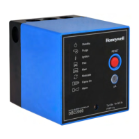
Honeywell DBC2000 Series User Manual

Honeywell DBC2000 Series
24 pages
To Next Page IconTo Next Page
Page #1 background imageLoading...
Page #1 background image
ENI7003R8 KO65 2013
1
DIGITAL BURNER CONTROLLER
DBC2000 SERIES
1. APPLICATION
The Honeywell DBC2000 is a microprocessor-based
integrated burner controller for automatically fired
gas, oil or combination fuel industrial single burner
power burner applications. The DBC2000 system
consists of the relay module and wiring subbase.
The DBC2000 Standard Model provides the
minimum requirements to control an industrial
burner system, such as automatic burner
sequencing, flame supervision, system status
indication, system or self-diagnostics and
troubleshooting. The DBC2000 Enhanced Model
includes an integrated Valve Proofing System,
whilst the Ultimate model includes bus
communication on top of this.
The DBC2000 is programmed to provide a level of
safety, functional capability and features beyond
the capacity of conventional controls.
2. FEATURES
Employs a plug-in mounting method
Uses a microprocessor to improve performance
Status and fault indication by indicator LEDs
A 4-wire firing rate switching circuit controls an air
damper motor or other auxiliary equipment during
start-up of the burner.
Safe start check before and during pre-purge
Dual flame amplifier for UV, IR or flame rod sensor
Automatic recycle once per 24h of uninterrupted
heat demand.
Frontal jack plug (Ø 3.5mm) to read the flame
signal with a microampere meter.
An electrical sub base lock (reset and safety limit
terminals are swapped) to avoid that a Standard
model is used systems wired for an Enhanced or
Ultimate model. The DBC2000 cannot start then.
Safety shutdown occurs on
- malfunction of the burner controller
- failure to ignite the pilot burner or main burner
- loss of flame during run period
- opening of air flow switch during pre-purge, start-
up, run and post-purge period
- flame signal detection during standby or pre-
purge period
Integrated Valve Proofing System (Enhanced and
Ultimate models only)
Remote bus communication (Ultimate model only)
Contents
1. Application 1
2. Features 1
3. Specifications 2
4. Dimensions 5
5. Installation and wiring 6
6. Operation 12
7. Trouble shooting 14
8. Approvals and Maintenance 16
Appendix: VPS calculation and diagrams 18
INSTALLATION INSTRUCTIONS
Important note:
Subject to changes without notice.
Please check our web site
http://hic.emea.honeywell.com
for the most recent version of this document.
All rights reserved.

Other manuals for Honeywell DBC2000 Series

Questions and Answers:

Honeywell DBC2000 Series Specifications

General IconGeneral
ModelDBC2000 Series
Output TypeRelay
TypeBurner Controller
ApplicationIndustrial Burner Control
Power Supply24 VAC/VDC
Communication ProtocolModbus RTU
ApprovalsUL, CE, FM
Humidity Range5 to 95% RH, non-condensing

Summary

APPLICATION

Product Overview

The Honeywell DBC2000 is a microprocessor-based integrated burner controller for automatically fired gas, oil or combination fuel industrial single burner power burner applications.

FEATURES

Mounting and Performance Enhancements

Employs a plug-in mounting method and uses a microprocessor to improve performance.

Status and Fault Indication

Status and fault indication provided by indicator LEDs and a frontal jack plug for flame signal measurement.

Key Operational Capabilities

Highlights features like 4-wire firing rate control, safe start checks, dual flame amplifier, and automatic recycle.

Safety Shutdown Triggers

Details safety shutdown conditions including burner malfunctions, pilot/main burner ignition failure, and flame loss.

Model-Specific Features

Covers Integrated Valve Proofing System (Enhanced/Ultimate) and Remote Bus Communication (Ultimate only).

SPECIFICATIONS AND MODEL SELECTION

FLAME DETECTION SYSTEM DETAILS

Ultraviolet Flame Detectors

Details wiring and types for Ultraviolet detectors like C7027A, C7035A, C7044A, and C7012A/G.

Flame Rod Detector Information

Provides wiring and connection details for Flame Rod type flame detectors.

TECHNICAL SPECIFICATIONS AND SAFETY

Power, Environmental, and Approvals

Covers supply voltage, allowable temperature/humidity, EN298 classification, approvals, power consumption, and protection class.

Unit Dimensions and Indicators

Details physical dimensions, mounting method, status indicator LEDs, and the jack plug function.

Reset Switch and Safety Precautions

Explains the reset switch operation, lockout conditions, and provides crucial cautions regarding electrical safety.

PHYSICAL DIMENSIONS AND LAYOUT

External Unit Dimensions

Illustrates the external dimensions of the controller in millimeters with a visual diagram.

Sub-base Mounting and Terminal Layout

Shows mounting dimensions and the detailed terminal layout of the sub-base for wiring.

INSTALLATION AND WIRING GUIDELINES

General Installation Precautions

Provides essential installation instructions, warnings for fire/explosion, and cautions for electrical shock hazards.

Wiring Requirements and Compliance

Details wiring connections, compliance with codes, load limits, external timers, installation restrictions, and grounding.

SUB BASE AND MODULE INSTALLATION

Fixing the Sub Base

Instructions for loosening screws, separating components, punching knockouts, and mounting the sub-base.

WIRING THE BURNER CONTROLLER

Relay Module Bottom Terminals

Guides on wiring for UV detectors and remote communication at the bottom terminal block.

Sub Base Terminal Connections

Comprehensive guide on connecting various components to sub-base terminals, including warnings and best practices.

TERMINAL IDENTIFICATION AND WIRING EXAMPLES

Standard Model Terminal Layout

Lists and describes terminals for the DBC2000E Standard model.

Enhanced/Ultimate Model Terminal Layout

Lists and describes terminals for the DBC2000E Enhanced and Ultimate models, noting terminal swaps.

Wiring Diagrams Overview

References diagrams for terminal layout and examples of wiring to external equipment for different models.

WIRING DIAGRAMS FOR EXTERNAL EQUIPMENT

Ignition and Firing Rate Control Wiring Examples

Illustrates wiring configurations for interrupted pilot, direct ignition, firing rate control, and air flow switch check.

Flame Detector Wiring Configurations

Details wiring for various flame detectors including rectification type, UV, and IR detectors, with safety cautions.

FLAME SIGNAL MONITORING AND DIAGNOSTICS

Flame Current Interpretation

Explains flame current monitoring, comparing jack plug readings to actual sensor wiring, with notes on variations.

Measuring Flame Signal with Multimeter

Demonstrates how to measure the flame signal using a multimeter via the jack plug and discusses component location.

CONFIGURING OPTIONAL FEATURES

Post-Purge and No Post-Purge Settings

Details how to configure post-purge or no post-purge modes for Standard and Enhanced/Ultimate models.

Pilot Ignition vs. Direct Burner Ignition

Explains the setup for Pilot Ignition (PI) and Direct Burner Ignition (DBI) modes, including model-specific configurations.

Valve Proofing System (VPS) Configuration

Guides on setting up the Valve Proofing System (VPS) for ENH/ULT models using DIP switches and pressure switches.

NORMAL OPERATION PROCEDURES

Operation Sequence Overview

Details the normal operation sequence of the DBC2000 controller, including inputs and device actions.

Understanding Indicator LED Status

Explains the meaning of indicator LEDs during normal operation and their arrangement on the controller.

OPERATIONAL SEQUENCE DIAGRAMS

Post-Purge Operation Sequence Diagram

Visual representation of the normal operation sequence with post-purge enabled.

No-Post-Purge Operation Sequence Diagram

Visual representation of the normal operation sequence when no post-purge is enabled.

TROUBLESHOOTING AND ERROR HANDLING

Error Types and Safe Shutdown Procedures

Explains critical and non-critical error types, safe shutdown, and the role of LEDs in fault indication.

Using LEDs for Fault Diagnosis

Notes that status LEDs indicate information to the operator for troubleshooting various errors.

ERROR CONDITIONS AND LED STATUS TABLE

Error Conditions and LED Indicators

Provides a table mapping error conditions to specific indicator LED status patterns for troubleshooting.

Handling Errors During Standby

Describes how errors occurring during standby mode are indicated by LEDs without causing a lockout.

APPROVALS AND DECLARATION OF CONFORMITY

Regulatory Compliance and Surveillance

Declares product conformity to directives and mentions product surveillance by KIWA Nederland BV.

MAINTENANCE, SERVICE LIFE, AND WARRANTY

Product Lifetime, Inspection, and Replacement

Details designed lifetime, required inspections, and replacement procedures after the product's lifespan.

Warranty Information Clarification

Notes that warranty terms are separate from the designed product lifetime and are detailed in delivery terms.

APPENDIX: VALVE PROOFING SYSTEM CALCULATIONS

General VPS Calculation Principles

Explains allowable leak-rate, factors affecting test time, and provides general formulas for VPS calculations.

VPS Calculation Examples

Presents calculation examples for minimum test time (Tp) in different pipe train configurations for VPS.

VOLUME DATA FOR VPS CALCULATIONS

Table a. Valve Volumes by Size and Length

Provides a table of volumes in dm3 for gas valves based on diameter, pipe length, and connection type.

MANUFACTURER CONTACT DETAILS

Honeywell Industrial Combustion Contact Information

Provides the address, city, country, and website for Honeywell Industrial Combustion.

Related product manuals