ENI7003R8 KO65 2013
SETTING THE OPTIONAL FEATURES
1. Post-purge or no post-purge
Post-purge mode
(default for all DBC2000E
models): before going to standby after heat
demand has ended, the DBC2000E performs a
15s post-purge cycle to ventilate the burner
chamber, with the blower switched on and the
firing rate in low position to save energy.
No post-purge mode
(selectable option): the
DBC2000E goes to standby with the blower
switched off immediately after heat demand ends
and the firing rate goes to low position.
STD model:
To enable no post-purge, apply line voltage to
terminal 12 on the wiring base. Practically this
means that a jumper is placed between terminals
1 (L) and 12.
ENH/ULT models:
To enable no-post-purge, make the correct DIP-
switch setting on the front of the DBC2000E.
SW1 = POSTPURGE select.
Factory set to post-purge (SW1=off).
See fig. 4-5 to locate the DIP switches.
2. Pilot Ignition (PI) or Direct main
Burner Ignition (DBI)
PI mode
(default): the main burner is ignited
indirectly by using an interrupted or intermittent
pilot flame. After the pilot is ignited and
stabelized, the DBC2000E goes for a second trial
of ignition (2
nd
safety and main stabilization are
3s) to ignite the main burner.
DBI mode
(selectable option): the intermittent
pilot ignition cycle is used to ignite the main
burner directly via the spark igniter. The second
trial for ignition has become redundant in this
mode. In DBI mode the 2
nd
safety and main
stabilization times are 0s and DBC2000E goes
straight into running/modulate after pilot
stabilization.
STD model:
To enable DBI mode, apply line voltage to
terminal 22 on the wiring base. Practically this
means that a jumper is placed between terminals
1 (L) and 22.
ENH/ULT models:
To enable DBI mode, make the correct DIP-switch
setting on the front of the DBC2000E.
SW2 = DBI/PI select. Factory set to PI (SW2=off).
See fig. 4-5 to locate the DIP switches.
3. Valve Proofing System – VPS
(ENH/ULT models only
)
Connect a gas pressure switch (such as the
C6097A2210) to terminal 22 on the wiring base
(N.O. contact).
Rule of thumb: adjust the pressure switch to 0.5x
the inlet pressure.
Table 5: VPS function:
VPS is not used (default)
SW4 = on
SW5 = off
performed during pre-purge
cycle, right after the heat
SW4 = off
performed right after the heat
SW4 = on
performed before and after
Table 6: VPS timing:
VPS test time
10s (default)
SW 1: Post-purge use (default: off = post-purge enabled)
SW2: DBI/PI select
(default: off = PI enabled)
SW3: VPS use
(default: off = disabled)
SW4: VPS pre-config
(default: off = disabled)
SW5: VPS post-config
(default: off = disabled)
SW6: VPS test time
(default: off = see timing table)
SW7: VPS test time
(default: off = see timing table)
SW8: Not used (for future use)
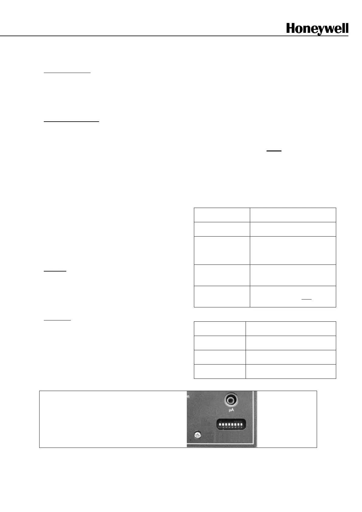
Fig 4-5 Configuration DIP switches (VPS) on the front of the DBC2000E (ENH/ULT only)

 Loading...


