Configuration
8/05 DC1010/1020/1030/1040 Product Manual 33
4.3.4 Program Alarm
4.3.4.1 Segment End Alarm (Alarm Code 07)
Once the selected segment is completed, the alarm becomes activated
- ALD1 – ALD3 Set the Alarm Code 07
- AL1 – AL3 Enter Segment No.for alarms
- ALT1 – ALT3 Define the alarm timing
(0= Flickering, 99.59 = Continuous, Others = Time Delay*)
* If ALD1-ALD3 is "07" (in other words, the alarm is set as "segment end alarm"), the ALT means how long
the alarm is enabled (activated immediately and last during specified time).
* In case ALD1 - ALD3 is not "07" (in other words, the alarm is not set as "segment end alarm"), the ALT
means "Time Delay".
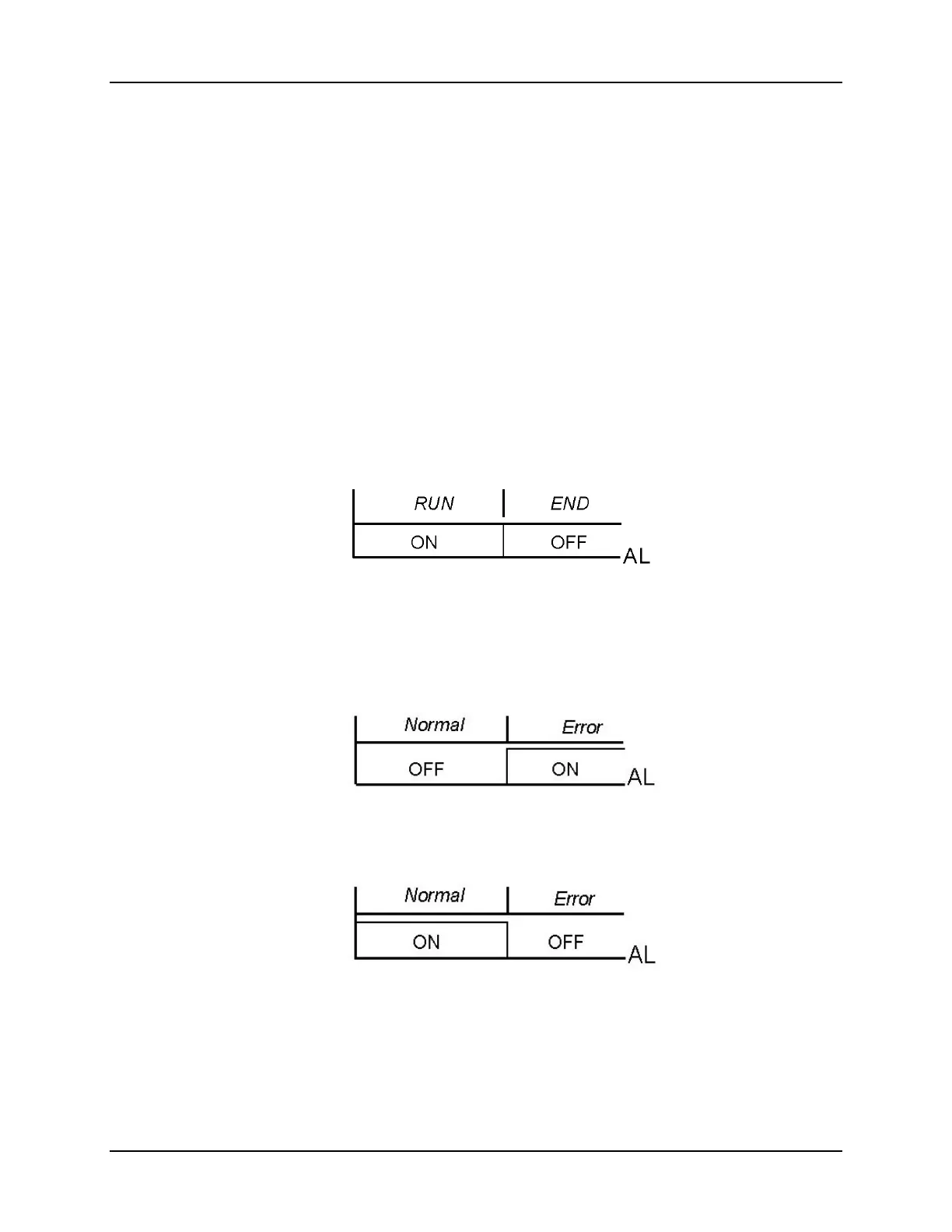
4.3.4.2 Program RUN Alarm (Alarm Code 17)
While a program runs, the alarm becomes actuated
Figure 4-15 Program RUN Alarm – Code 17
4.3.5 System Alarm
4.3.5.1 System Error Alarm (Alarm Code 08)
Figure 4-16 System Error Alarm – Code 08
4.3.5.2 System Error Alarm (Alarm Code 18)
Figure 4-17 System Error Alarm – Code 18
4.3.5.3 Timer Alarm (Alarm Code 19)
Once the PV reaches the SP, the alarm becomes actuated after a certain time delay.
(Range: 00 hour 00 min – 99 hour 59 min)
 Loading...


