DISTRIBUTED I/O
EN0B-0090 4
TECHNICAL DATA
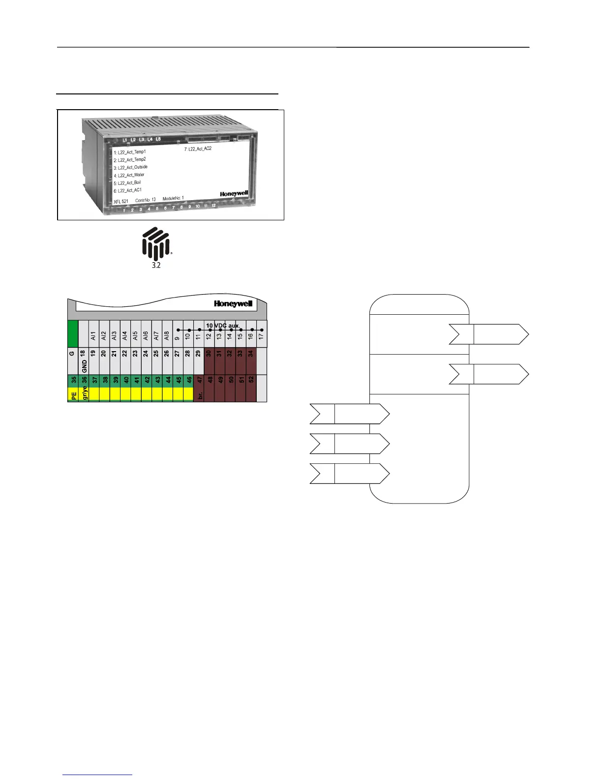
Analog Input Module XFL521B
• Eight inputs (AI1 – AI8)
0 to 10 Vdc (see EN1R-1047 for impedance
information)
0 to 20 mA (via external 500-ohm resistor)
4 to 20 mA (via external 500-ohm resistor)
NTC 20K ohm (-50°C to +150°)
PT1000 (-50°C to +150°C)
• Protected inputs up to 40 Vdc / 24 Vac
• 12-bit resolution
• ± 75 mV accuracy (0 to 10 V)
• 10 Vdc auxiliary voltage supply (9 – 17) , I
max
= 5 mA
• 1 sec polling time with CPU
• Green power LED (L1) and red LONWORKS status LED
(L2)
• Dimensions (WxLxH): 47x97x70 mm
The analog input module has eight input channels which
can be used for connecting sensors or any device pro-
viding an analog output. The input values are read by the
CPU and can then be used for monitoring or as para-
meters for controlling other devices.
The unit plugs into the XSL513 Terminal Block and can be
inserted and removed without disturbing other units on the
bus. Terminals AI1 through AI8 are the analog inputs and
terminals 9 through 17 are wired together and provide an
auxiliary voltage of 10 Vdc. The module address is set
using the rotary HEX switch.
NOTE: When the input is identified as a DI point, the
internal pull-up resistor is disabled.
Open Loop Sensor
Object Type #1
Mandatory
Network
Variables
input
NV 1
nviRequest
SNVT_obj_request
nv1
nvoAiValue
SNVT_volt_f
input
NV 1
nviRequest
SNVT_obj_request
nv1
nvoAiTemp
SNVT_temp_p
Optional
Network
Variables
Optional
Configuration
Properties
input
NV 1
nviRequest
SNVT_obj_request
nc1
UCPTSensorConfig
input
NV 1
nviRequest
SNVT_obj_request
nc2 UCPTSendOnDelta
input
NV 1
nviRequest
SNVT_obj_request
nc3 UCPTWireOffset
Figure 2. LONMARK Object for each analog input.
For each Sensor Object, the XFL521 Analog Input Module
provides an additional output NV, SNVT_temp_p, which
communicates the temperature in °C. This allows this
module to be used as a true temperature sensor in an
open L
ONMARK integration. If the Sensor Object is con-
figured as 0 to 10V, this NV will be invalid (0x7FFF).
 Loading...


