DISTRIBUTED I/O
EN0B-0090GE51 R0802 16
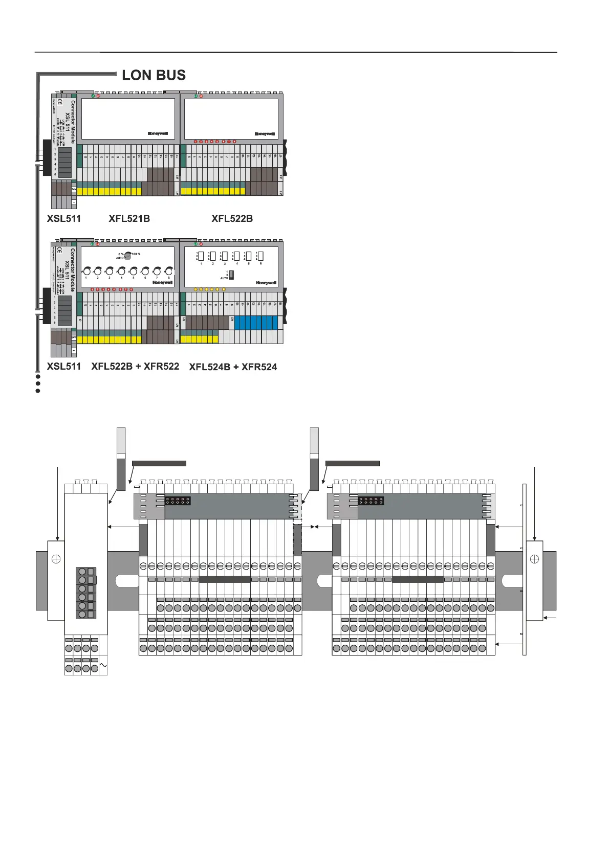
Fig. 9. Terminal blocks with LONWORKS connector
6. Push the sliding bus connector to the left until it locks
onto the matching circuit board section on the adjacent
connector module (see Fig. 10).
7. If necessary (e.g. in case of vibrations due to
refrigerating equipment, etc.), mount braces (see Fig.
11).
8. Lock in all other modules and connect them using the
sliding bus connector. Slide each sliding bus connector
as far to the left as possible.
NOTE: The electronics module or the manual terminal dis-
connect module will not fit properly on the terminal
block if the sliding bus connector is not on the left
side.
9. Fit the end cover included with the XSL511 onto the last
module.
10. Install 3
rd
-party DIN rail end bracket close to end cover
of the last module.
NOTE: It is recommended that you use solid standard 3
rd
-
party DIN rail end brackets on both ends of the
terminal block to prevent any movement of the
terminal blocks. Terminal blocks must abut each
other to ensure proper contact at the sliding bus
connector.
11. Mount the type-C safety latches to provide extra
assurance that adjacent terminal blocks will not
become separated.
type-C safety latch
race
type-C safety latch
race
24V
Connector Module
XSL 511
DIN rail
end bracket
DIN rail
end bracket
Fig. 10. Sliding bus connector connects adjacent modules

 Loading...


