DISTRIBUTED I/O – PRODUCT DATA
EN0B-0090GE51 R0316 10
Digital Input Module XFL523B
Twelve inputs (DI1 – DI12)
R
i
= 10kΩ
Max. 20 Hz input frequency
ON/OFF state: OFF: U
i
2.5 Vdc; ON: U
i
5 Vdc
Protected switching up to 40 Vdc / 24 Vac
LED per channel, color selectable in two groups (LED
switch 1: DI 1 – 6; LED switch 2: DI 7 – 12); color
combinations: see Table 9
18 Vdc auxiliary voltage supply (unregulated)
1 sec polling time with CPU
Green power LED (L1) and red L
ONWORKS status LED (L2)
Dimensions (WxLxH): 47x97x70 mm
XFL523B
DI1
DI2
DI3
DI4
DI5
DI6
DI7
DI8
DI9
DI10
29
28
27
26
25
24
23
22
21
20
19
18GND
G
30
31
32
33
3452
51
50
49
48
47
br.
46
45
44
43
42
41
40
39
38
37
36
35
PE
gr/ye
DI11
DI12
13
14
15
16
17
18 Vdc auxiliary
max. 20 Hz
DI1
1 2
18 35 13...17 18...29DI1...DI12 DI1...DI12
5 to 24 V
min.
25 ms
min.
25 ms
5 to 24
Vdc
~230 V
gold contacts
(suitable for
low voltage)
21
O
N
BEHIND FRONT COVER:
LED switch 1 (default: OFF)
LED switch 2 (default: OFF)
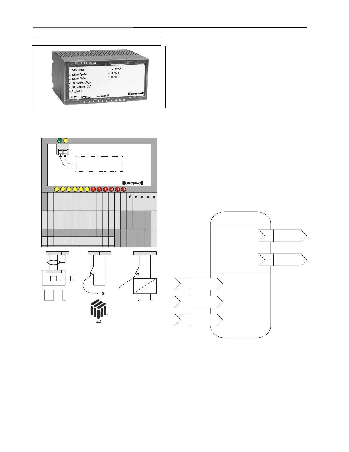
Fig. 12. XFL523B terminals / wiring examples
The digital input module has twelve input channels which can
be used for connecting sensors or any device providing a
digital output. The input values are read by the CPU and can
then be used for monitoring or as parameters for controlling
other devices.
The unit plugs into the XSL513 Terminal Block and can be
inserted and removed without disturbing other units on the
bus. Terminals DI1 through DI12 are the digital inputs.
Terminals 13 through 17 are internally connected with each
other and provide an auxiliary voltage of 18 Vdc. Terminal 18
(the ground) and terminals 19 through 29 are internally
connected with each other and provide the ground signal. The
module address is set using the rotary HEX switch (in the
case of applications prior to CARE 4.0).
Beginning with Excel 500 controller firmware version 2.04.00,
the online point attribute Normally Open / Normally Closed
(NO/NC) defines the relation between the physical state
(contact position) and its logical status. See Table 9.
Open Loop Sensor
Object Type #1
Mandatory
Network
Variables
input
NV 1
nviRequest
SNVT_obj_request
nv1
nvoDiValue
SNVT_switch
input
NV 1
nviRequest
SNVT_obj_request
nv1
nvoDiValueCnt
SNVT_count
Optional
Network
Variables
Optional
Configuration
Properties
input
NV 1
nviRequest
SNVT_obj_request
nc1
UCPTSensorConfig
input
NV 1
nviRequest
SNVT_obj_request
nc2 UCPTSendOnDelta
input
NV 1
nviRequest
SNVT_obj_request
nc27 SCPTDirection
Fig. 13. L
ONMARK Object for each digital input
For each Sensor Object, the XFL523B Digital Input Module
provides an additional output NV, SNVT_switch. For an open
L
ONMARK integration, this offers a more convenient way of
accessing the sensor value compared to using the NV
SNVT_count. If the Sensor Object is configured as “Totalizer”,
this NV is invalid (state = 0xFF, value = 0).
 Loading...


