IFP-FFT Manual — P/N 54708:B3 10/28/2021 21
Section 5: Audio Phone Circuit Installation
The IDP-FFT works with the FFT-FPJ Fire Fighters Telephone Jack.
5.1 Maximum Number of Devices
The IFP-FFT supports up to 72 zones. Each zone consists of one Addressable Monitor Module (IFP-MINIMON) and a minimum of one Fire
Fighter Telephone Jack (FFT-FPJ).
5.2 Wiring Requirements for the Audio Telephone Circuit
No special wire is required for the Audio Telephone Circuit. The wire can be untwisted, unshielded, twisted, or shielded as long as it meets
the National Electric code 760-51 requirements for power limited fire protective signaling cables.
54 Ohm maximum impedance - 12 to 18 AWG.
Twisted, shielded wire is recommended for maximum protection against EMI and AFI emissions and susceptibility.
If using shielded cable, attach the shield to grounding stud below TB6 of the IFP-FFT.
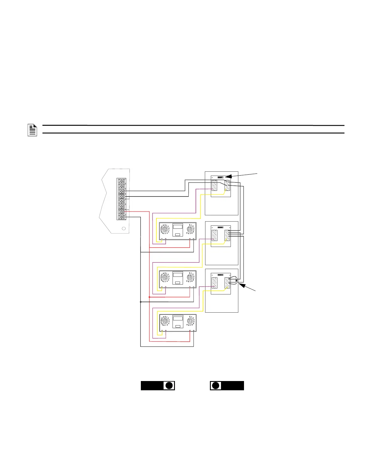
5.2.1 Single Phone Jack Audio Circuit in Class B Configuration
Figure 5.1 illustrates the single phone jack configuration wiring audio circuit and the SLC for Class B Configuration. The audio circuits must
be connected to the FFT phone out terminals for all Class B audio configurations.
NOTE: Do not ground shield on both ends.
1 3
2 2
3 1
TB2
TB1
1 3
2 2
3 1
TB2
TB1
1 3
2 2
3 1
TB2
TB1
SLC OUT
+
–
+
–
+
+
PHONE
–
SLC
IN PH O N E
IN
–
OUT
ADDRESS
LOOP
ONES
TENS
ADDRESS
LOOP
ONES
TENS
ADDRESS
LOOP
ONES
TENS
Contact EOL Connected
(See Figure 5.2 for EOL reference.)
Do not loop wire under the terminals.
Break wire run to provide proper
supervision of communications.
4.7kΩ, 1/2 watt ELR
Install on the last device for
Class B telephone circuit only.
Figure 5.1 Single Phone Jack Audio Circuit Wired in Class B Configuration
+ audio
- audio
+ SLC
- SLC
IFP-MINIMON
IFP-MINIMON
IFP-MINIMON
IFP-FFT
FFT-FPJ
FFT-FPJ
FFT-FPJ
connected not connected
Figure 5.2 EOL Reference
 Loading...