IFP-FFT Manual — P/N 54708:B3 10/28/2021 23
Wiring Requirements for the Audio Telephone Circuit Audio Phone Circuit Installation
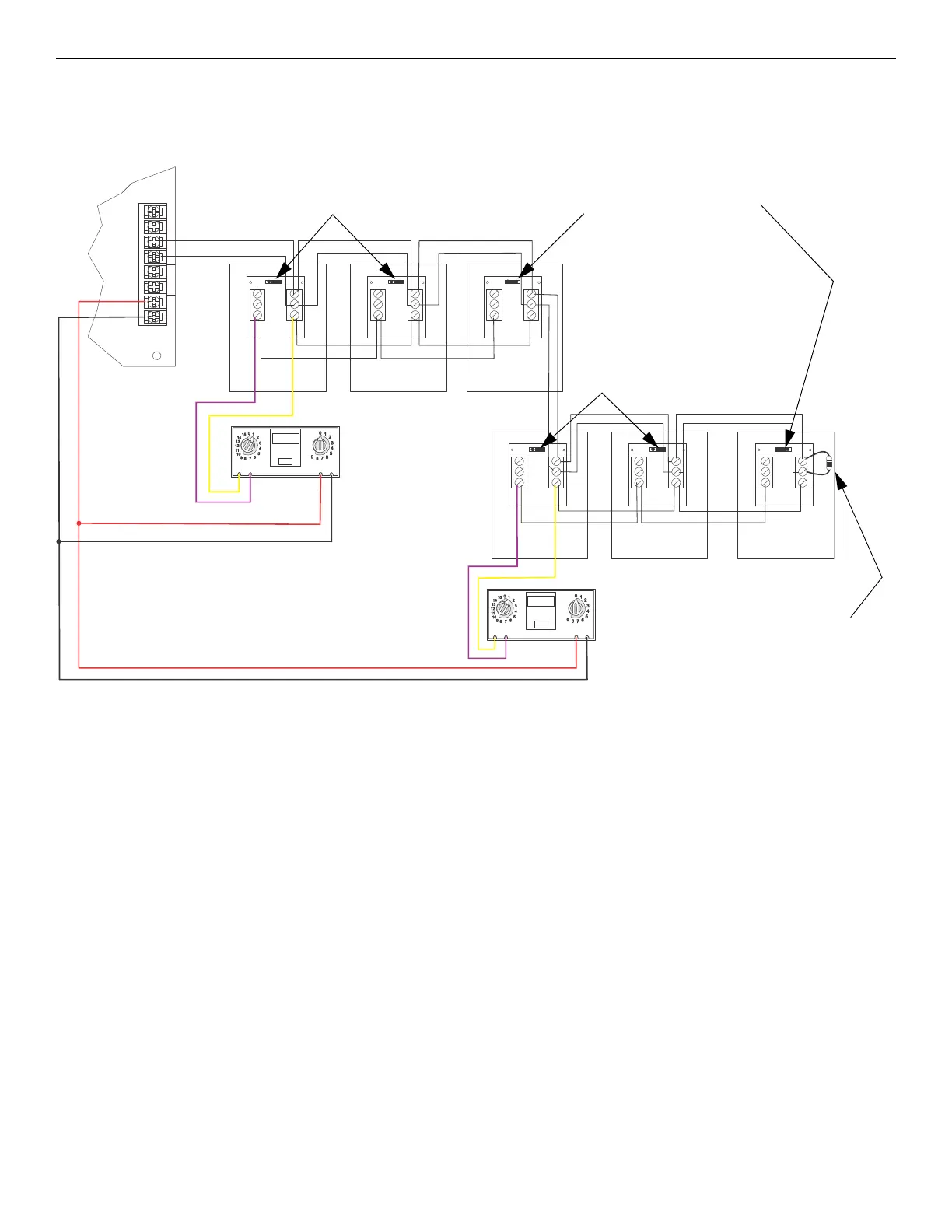
5.2.3 Multi-Phone Jack Audio Circuit in Class B Configuration
For wiring specifications, refer to Section Section 5.2. Figure 5.4 illustrates how to wire the multi-phone jack audio circuit and the SLC for
Class B configuration. In the multi-phone jack configuration, the maximum mini-monitor contact wiring resistance between the first and last
FFT-FPJ must be less that 100 ohms.
SLC OUT
+
–
+
–
+
+
PHONE
–
SLC
IN PH ON E IN
–
OUT
1 3
2 2
3 1
TB2
TB1
1 3
2 2
3 1
TB2
TB1
1 3
2 2
3 1
TB2
TB1
1 3
2 2
3 1
TB2
TB1
ADDRESS
LOOP
ONES
TENS
4.7kΩ, 1/2 watt ELR
Install on the last
device on a Class B
telephone circuit only.
Figure 5.4 Multi-Phone Jack Audio Circuit Wired in Class B Configuration
Contact EOL Connected
(See Figure 5.2 for EOL reference.)
Do not loop wire under the terminals.
Break wire run to provide proper
supervision of communications.
+ audio
- audio
IFP-MINIMON
IFP-MINIMON
IFP-FFT
FFT-FPJFFT-FPJ
FFT-FPJ FFT-FPJ FFT-FPJ
FFT-FPJ
Contact EOL Not Connected
(See Figure 5.2 for EOL reference.)
+ SLC
- SLC
Contact EOL Not Connected
(See Figure 5.2 for EOL reference.)
 Loading...