IFP-FFT Manual — P/N 54708:B3 10/28/2021 17
FFT-FPJ Installation Installation
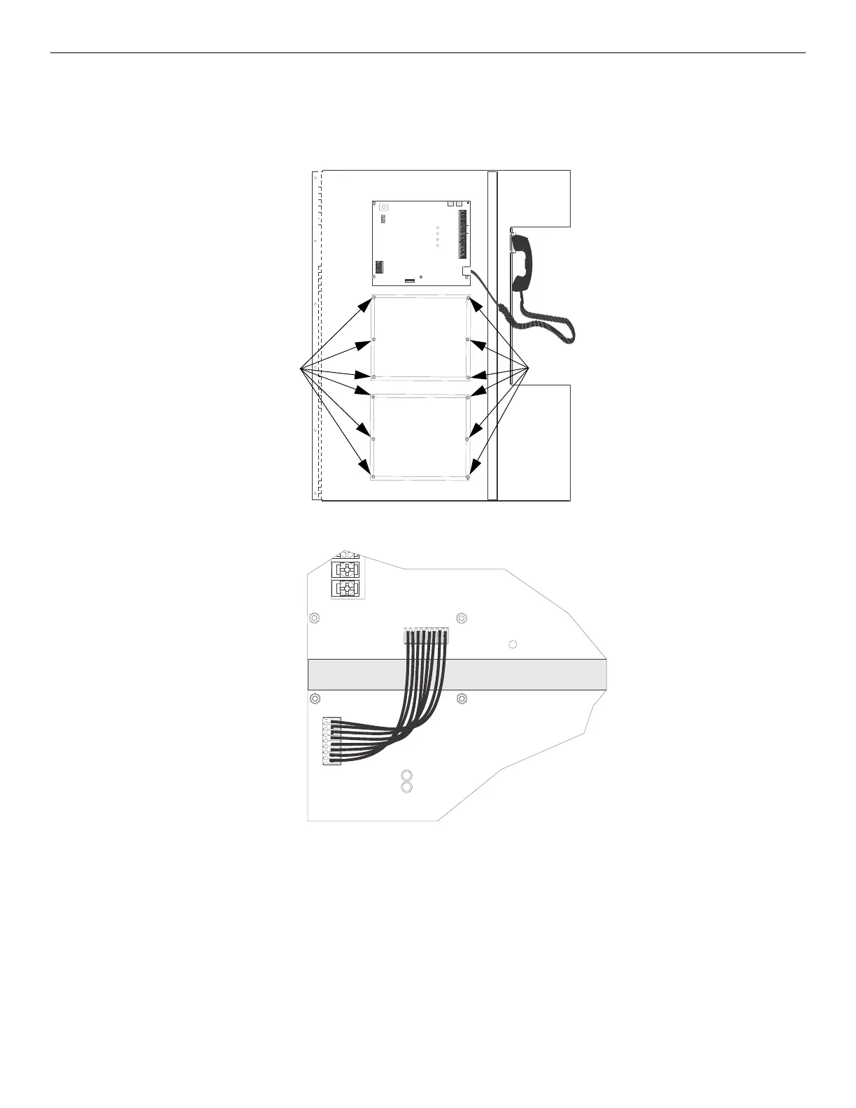
To Install the FFT-24:
1. Open the cabinet door and dead front panel.
2. Disconnect power. See Table 1.2 on page 6 for compatible powering devices.
3. Remove the blank plate and discard.
4. Mount the FFT-24 on the six mounting studs located on the inside of the dead front panel.
5. Secure the FFT-24 using the nuts removed from the blank plate.
6. Connect one end of the wiring harness (P/N 130398 supplied) to the IFP-FFT and the other end to the FFT-24 as shown below.
7. Restore power. See Section 3.7.
3.11 FFT-FPJ Installation
The FFT-FPJ Firefighter Phone Jack mounts in a single-gang electrical box (4" x 2.125" x 2.5") or in a deep single-gang electrical box (4" x
2.125" x 3.75") if installed with an addressable mini-monitor module.
Connect the telephone audio loop between the FFT-FPJ and IFP-FFT as detailed in Figure 3.17. All circuits are power-limited and super-
vised.
TROUBLE
NO COM NC
–
+
A
B
SLC OUT
+
–
+
–++
PHONE
–
SLC IN OUT PHON E IN
–
1
2
3
4
mounting studs mounting studs
Figure 3.14 Mounting Locations for an FFT-24
IFP-FFT
FFT-24
Figure 3.15 Wire Harness Connection from the IFP-FFT to an FFT-24 Zones 25- 48
 Loading...