Do you have a question about the Honeywell Fire-Lite Alarms SD365 and is the answer not in the manual?
Describes the sensor's tamper-resistant capability preventing removal without a tool.
Tests sensor electronics and panel connections using a test magnet.
Details methods for testing smoke detection with aerosol agents.
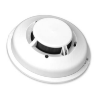
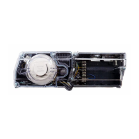
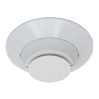
The SD365 and SD365-IV are intelligent photoelectric smoke sensors designed for use in fire alarm systems. These plug-in type sensors combine a photoelectronic sensing chamber with addressable-analog communications, allowing them to transmit an analog representation of smoke density to a control panel. They are UL 268 listed for Open Air Protection and UL268A listed for Duct Applications, making them suitable for various installation environments, including inside DNR(W) duct smoke detectors.
The primary function of these sensors is to detect smoke by continuously monitoring the air for changes in smoke density. When smoke is detected, the sensor transmits an analog signal to a compatible control panel, indicating an alarm condition. The sensors are equipped with rotary dial switches for setting a unique address, allowing the control panel to identify the exact location of the alarm. Two LEDs on the sensor provide visual status indications, controlled by the panel, and can be set to red, green, or amber, operating in on, off, or blinking modes. An output is also provided for connecting an optional remote LED annunciator (P/N RA100Z), which can be synchronized with the sensor's LED operation or controlled independently.
These sensors are designed for installation in compliance with the National Electrical Code, applicable local codes, and the requirements of the Authority Having Jurisdiction (AHJ). For optimal performance, installation should adhere to NFPA 72 guidelines. Fire-Lite recommends spacing sensors 30 feet apart (9.1 m) in low airflow applications with smooth ceilings.
The SD365 model supports LiteSpeed® protocol mode, while the SD365-IV supports both LiteSpeed and CLIP (Classic Loop Interface Protocol) modes. This compatibility ensures proper communication with listed-compatible control panels. Devices are point addressable, supporting up to 159 addresses.
Installation involves wiring the sensor base (supplied separately) as shown in the wiring diagram, setting the desired address on the rotary switches, and then installing the sensor into the base by pushing and turning it clockwise to secure it. It is crucial to remove power from the communication line before installation and apply power only after all sensors have been installed.
The sensors include a tamper-resistant capability to prevent unauthorized removal from the base without a specialized tool. Refer to the base manual for details on utilizing this feature.
Regular testing and maintenance are essential to ensure the proper functioning of the SD365 and SD365-IV sensors. All sensors must be tested after installation and periodically thereafter, following methods approved by the AHJ and NFPA 72.
Before cleaning, notify the proper authorities and disable the zone or system to prevent unwanted alarms.
Dust covers provide limited protection during shipping but must be removed before the sensors can sense smoke. Sensors should also be removed prior to heavy remodeling or construction to prevent damage or contamination.
A sensor that fails any of these tests may require cleaning and retesting. After all maintenance is complete, restore the system to normal operation and notify the proper authorities.
| Type | Photoelectric |
|---|---|
| Operating Voltage Range | 15-32 VDC |
| Humidity | 10% to 93% non-condensing |
| Operating Temperature Range | 0°C to 49°C (32°F to 120°F) |
| Height (including base) | 5.1 cm (2.0 in) |
| Compatibility | Fire-Lite addressable panels |