
 Need help?
Do you have a question about the Honeywell Greenheck MS4120 and is the answer not in the manual?
Lists necessary wrenches and tools for installing Honeywell actuators.
Alerts users to potential death or injury from electrical shock during installation.
Guides mounting the standoff bracket for jackshafted or direct drive dampers.
Details attaching the actuator bracket using thread studs and nuts.
Explains how to set the actuator's rotation for the correct damper fail position.
Instructions for sliding and securing the actuator onto the damper drive shaft.
Illustrates electrical connections and describes expected actuator behavior.
Information on product updates, warranties, and contact details.
This document describes the installation, operation, and maintenance of Honeywell Actuators, specifically models MS4120, MS4620, MS8110, MS8120, MS7510, and MS7520, when used with Greenheck model VCD control dampers in duct-mounted or sleeved applications. The manual emphasizes safety, proper installation procedures, and electrical requirements to ensure reliable operation and prevent damage or injury.
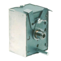
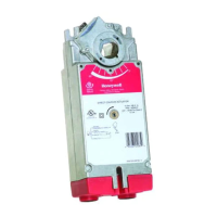
The Honeywell actuators are designed to control Greenheck VCD dampers by rotating a drive shaft, thereby opening or closing the damper blades. These actuators are crucial components in HVAC systems, enabling precise airflow regulation. They feature a spring-return mechanism, which ensures that the damper returns to a predetermined "fail position" (either open or closed) in the event of a power loss. This fail-safe operation is critical for maintaining system integrity and safety, for example, by ensuring fire dampers close or ventilation dampers open during an emergency. The installation instructions detail how to mount the actuator to the damper shaft, either directly or via a jackshaft, and how to configure its rotation for the desired fail position.
The manual provides a table outlining the electrical specifications for various actuator models, including voltage, running wattage, and holding wattage.
| Model | Volts | Running | Holding |
|---|---|---|---|
| MS4120F1006 | 120 VAC | 35W | 10W |
| MS4120F1204 | |||
| MS4620F1005 | 230 VAC | 35W | 10W |
| MS4620F1203 | |||
| MS7510A2008 | 14W | ||
| MS7510A2206 | 14W | ||
| MS7520A2007 | 24 VAC/VDC | 16W | 5W |
| MS7520A2015 | 22W | ||
| MS7520A2205 | 16W | ||
| MS7520A2213 | 22W | ||
| MS8110A1206 | 24 VAC/VDC | 30W | 8W |
| MS8120F1002 | 24 VAC | 45W | 10W |
| MS8120F1200 |
The torque specification for the actuator shaft clamp screw is 88 in./lbs. (9.9Nm), which is critical for ensuring a secure connection between the actuator and the damper shaft. The installation requires specific tools: 3/8 in. and 7/16 in. wrenches, and a 10mm wrench. The damper shaft should extend a minimum of 6 inches (152mm) beyond the duct or sleeve for proper actuator mounting.
The actuators are designed for external field installation on Greenheck VCD control dampers. They can be installed in various orientations relative to the duct (parallel, perpendicular up, or perpendicular down) to accommodate different clearance requirements. A key feature is the ability to adjust the universal clamp to change the power direction of clockwise rotation, allowing the actuator to be configured for either clockwise or counter-clockwise fail rotation. This flexibility ensures that the damper returns to the desired fail position (open or closed) upon power loss, aligning with specific system safety requirements.
The spring-return mechanism is designed to activate reliably. An important note highlights that a power break of less than one second may cause the actuator to spring-return only 5 degrees or less, remaining largely in its current position, while a longer duration power break will ensure a full return to the fail position. This distinction is important for understanding actuator behavior during momentary power fluctuations.
The installation process involves several steps:
The manual implicitly suggests that proper installation is key to long-term, low-maintenance operation. While explicit maintenance schedules are not provided, the detailed instructions for securing components, torquing fasteners, and verifying fail-safe operation contribute to the device's reliability and reduce the need for frequent intervention. The emphasis on checking damper blade compression and shaft rotation during installation ensures that the system operates efficiently from the outset, minimizing wear and potential issues.
The "Safety Warning" section highlights the importance of disconnecting the power supply before installation to prevent equipment damage, electrical shock, or serious injury. This is a fundamental maintenance and installation safety practice. The document also states that Greenheck reserves the right to change specifications without notice, indicating a commitment to continuous improvement, which may lead to updated designs that enhance durability and ease of maintenance over time. Product warranties and additional resources are available online, providing further support for users.
 General
| Brand | Honeywell |
|---|---|
| Model | Greenheck MS4120 |
| Category | Controller |
| Language | English |


 To Next Page
