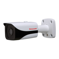
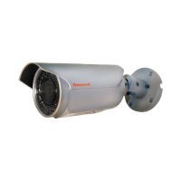
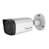
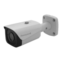
HBD2PR1(X) 1080p TDN IR Bullet IP Camera
www.honeywell.com/security
+1 800 323 4576 (North America only)
https://www.honeywellsystems.com/ss/techsupp/index.html
Document 800-17077V1 – Rev A – 07/2014
© 2014 Honeywell International Inc. All rights reserved. No part of this publication may be reproduced by any means without written permission from Honeywell. The information in this publication is believed to be accurate in all respects. However,
Honeywell cannot assume responsibility for any consequences resulting from the use thereof. The information contained herein is subject to change without notice. Revisions or new editions to this publication may be issued to incorporate such changes.
Before You Begin
Before you begin, check that you have received all of the parts listed below. If any parts are
missing or damaged, contact your dealer immediately.
Caution Installation and servicing should be performed only by qualified and
experienced technicians to conform to all local codes and to maintain your
warranty.
Required tools:
• A Phillips screwdriver
• A drill with an appropriately-sized drill bit for pre-drilling holes for the wall anchors.
Preparing the Mounting Surface
1. Place the mounting template on the mounting surface where you want to install the camera.
2. Drill a hole and pull the cables through the mounting surface.
3. Use the drill to pre-drill holes for the wall anchors, then insert the four wall anchors and secure
them in place.
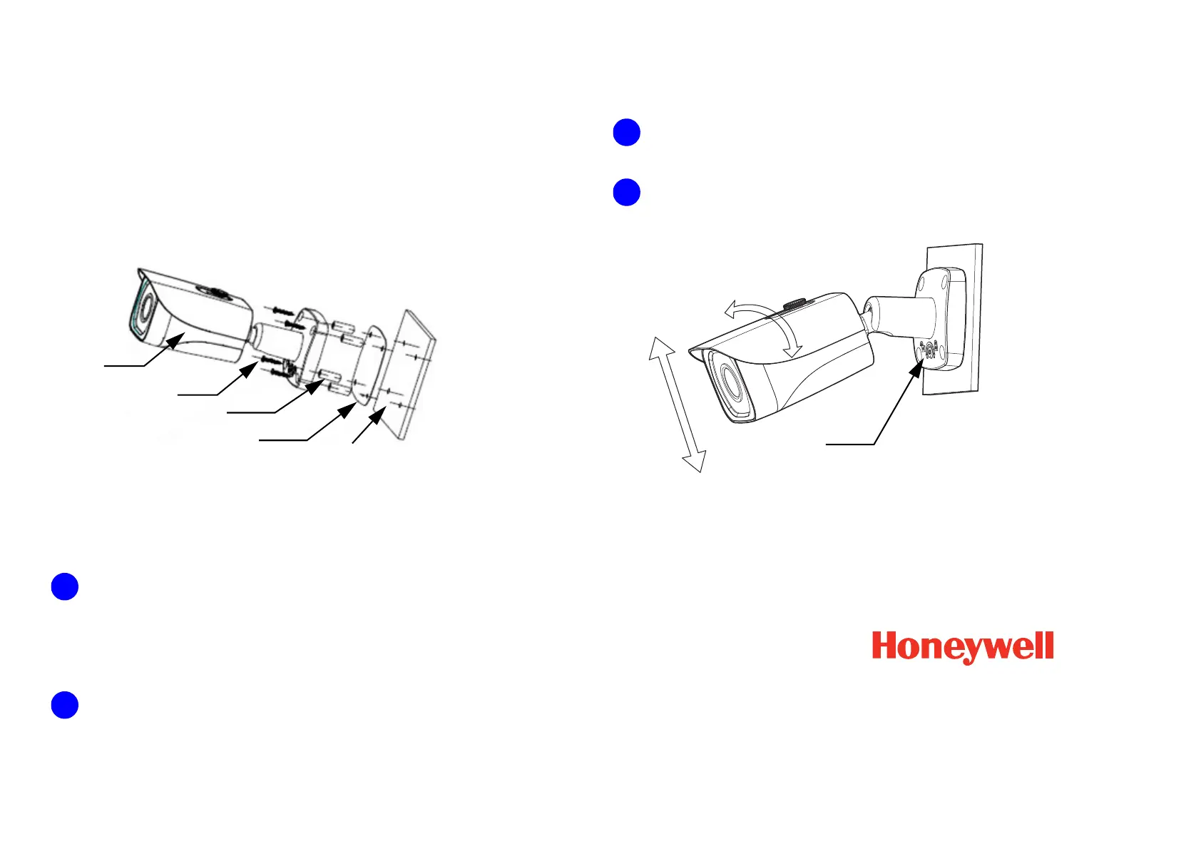
Mounting the Camera
1. Position the camera so that the screw holes on the base align with the screw holes on the
mounting template and the holes for the wall anchors.
2. Insert the four self-tapping screws through the holes in the bullet camera’s base, into the wall
anchors, and then tighten them to secure the bullet camera in place.
Connecting the Wires
Connect the IP cable to the RJ-45 port on the camera.
Adjusting the Field of View
1. Use the star-shaped Allen key (supplied) to loosen, but not remove, the adjusting screw on the
camera base.
2. Adjust the bullet camera to the desired field-of-view angle, and then re-tighten the adjusting
screw to secure the camera in place.
Note The adjusting screw must be loosened before you can adjust the camera field-of-view direction
and/or angle. Please secure it tightly when finished with these adjustments.
Note When the camera body and installation chassis for a 90° angle, and the adjusting screw is tight,
please do not rotate the camera body more than 360°.
•Camera
• Documentation CD
• Quick install guide
• Mounting template
• Self-tapping screws (×5)
• Plastic wall anchors (×5)
• Allen key
Wall or ceiling
Mounting template
Wall anchor
Installation screw
Camera

 Loading...