3. Connecting the Wiring
a. Pull the wires through the wire access hole (see 2. Preparing the Mounting
Surface (Surface Mount) for more information) until you have at least 4 inches
of wire.
b. Remove the green connector strip from the camera base and make the
necessary power connections.
c. To power the camera, you can supply power using 24 V AC or PoE.
Note It is NOT recommended that you supply power to the camera from both 24 V AC
and PoE at the same time.
d. Pull the cables through the back or side entries of the camera skirt, then
connect to the camera assembly.
Power
24 V AC
RJ45 Ethernet network
connection (using any
type of CAT5 cable). Also
for Power over Ethernet
(PoE 802.3 af).
Cover plate
4
Network Setup
Honeywell IP Utility
Note Before installing and using the Honeywell IP Utility, ensure that your camera is
connected to your network through a CAT5 Ethernet cable.
Note It is recommended that you disable any Norton’s AntiVirus software that might be
running on the workstation.
To discover the IP camera devices and configure their network settings, you must first install the
IP Utility. See the appropriate user guide located on the software DVD or on the Honeywell
product web site. You must have Windows administrator privileges for the workstation on which
the Honeywell IP Utility is being installed.
1. Insert the DVD. Autorun will start the installation. If autorun does not start, browse to the
DVD drive and run Honeywell IP Utility Setup.exe.
2. Follow the steps in the InstallShield Wizard.
3. Log on to the IP Utility:
a. Double-click the IP Utility icon ( ) on the desktop. The logon dialog box appears.
b. From the User Name list, select Admin or Guest.
c. Enter the case-sensitive Password and click . The default passwords are 1234
(Administrator) or guest (Guest user).
Note This camera supports the PSIA specification for interoperability between network video
products.
Configuring the Network
1. After you log on to the IP utility, the devices on the network are automatically discovered
and listed in the Discovery pane. After the initial discovery, auto-refresh continues to
discover newly added network devices.
2. Connect to your IP camera device by double-clicking it in the Discovery pane or by
selecting it and clicking .
3. Configure the IP network settings:
• Automatically. Connect to the device, click the System tab, select to Obtain an IP
Address automatically, enter the Device Name, and click Apply. The network
settings are automatically assigned from the network server.
• Manually. Connect to the device, click the System tab. Ensure Obtain an IP
Address automatically is not selected, then enter the Device Name, IP Address,
Subnet Mask, and Gateway values. Click Apply.
Caution Check the IP network settings before clicking Apply. Incorrect values might cause
a failure when connecting to the device.
Note Contact your network administrator if you have any network-related issues or questions
about your network.
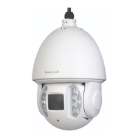
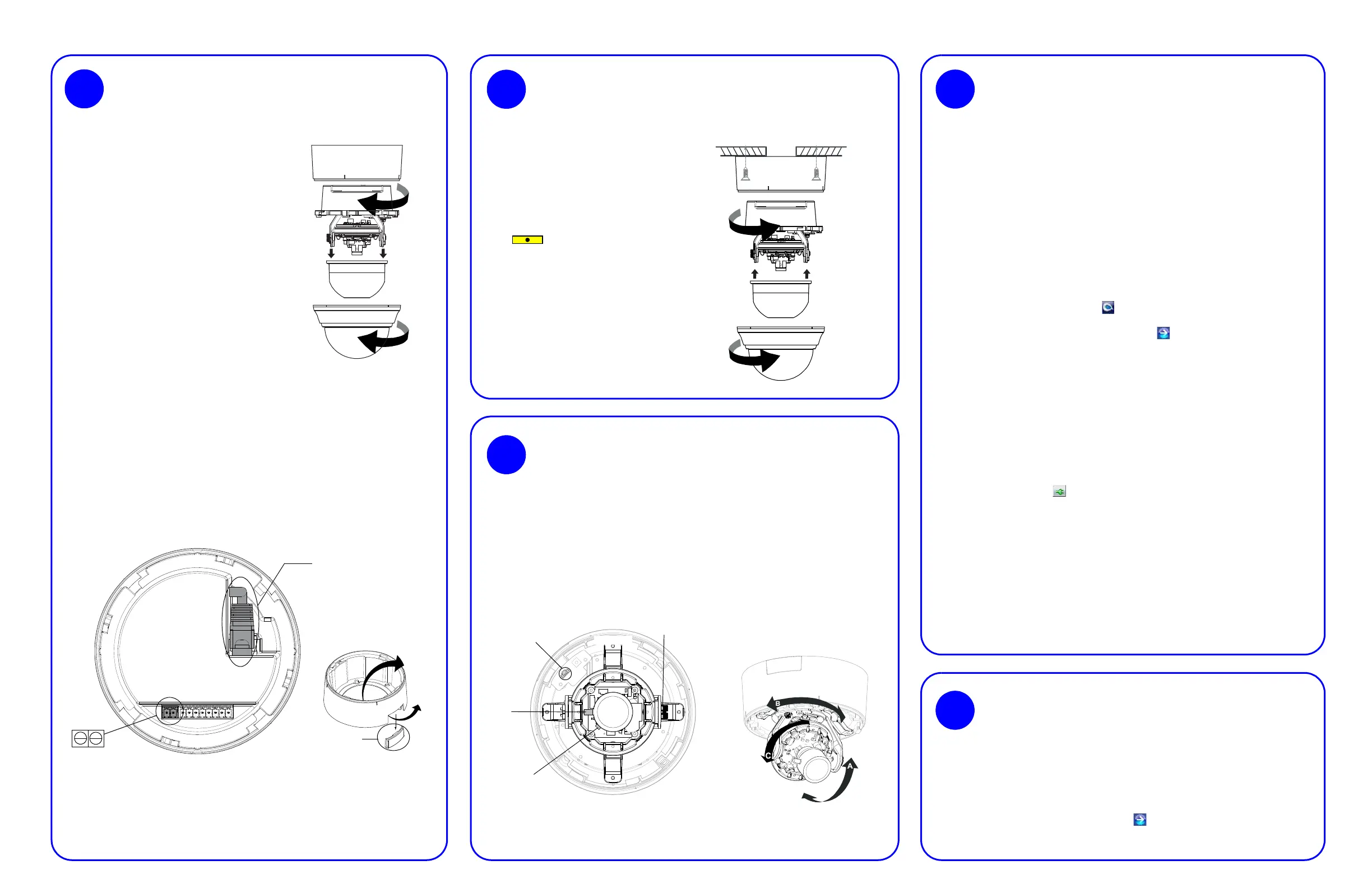
Camera Mounting
2
Surface Mount
Skirt
Camera assembly
Turret
Bubble
1. Secure the skirt to the ceiling (using
appropriate screws, not supplied) or wall
using the supplied screws.
Note When mounting, you must use screws
that are able to support at least three
times the weight of the camera.
2. Rotate and align the yellow label
( ) on the camera assembly with
the yellow label on the skirt.
3. Secure the camera assembly to the skirt
by pushing it into the skirt, then twisting it
clockwise until it clicks securely into
place.
4. Adjust the camera’s field of view, as
needed (see Camera Adjustment).
5. Install the turret by clicking it into place.
6. Install the bubble by placing it on the
camera with the tabs to the left of the
slots, then turning it clockwise until the
tabs click securely into place.
3
1. Apply power to the camera.
Note It is NOT recomended that you supply both 24 V AC and PoE at the same time.
2. Connect the BNC video cable to the local video out connector (see illustration below) and
view the video signal.
Note Please wait approximately 60 seconds after connecting to a power source for video to
appear on the local video out.
3. Loosen the thumbscrew that locks the gimbal assembly in place to adjust the tilt rotation.
4. Adjust the camera to the desired view. Orient as shown below to maintain the correct picture
orientation.
Camera Adjustment
Thumbscrew (loosen to
adjust tilt rotation)
Set focus
(top)
Set focal length
(bottom)
Local video out connector
(for adjusting aim
and focus)
Top view
Legend
A = Tilt rotation
B = Horizontal rotation
C = Pan rotation
5. Retighten the thumbscrew to lock the gimbal assembly in place.
6. Disconnect the BNC video cable.
The camera has a web client that enables you to view video and configure device settings for
the camera using a standard web browser. See the appropriate user guide located of the
software DVD to set up your web browser to view video. To log on to the web client application:
1. Launch Internet Explorer and enter the URL (IP address) for the network camera.
OR, launch the web client application from the IP Utility by clicking Launch Browser.
2. Select the User Name as Admin or Guest.
3. Enter the case-sensitive password and click . The default passwords are 1234
(Administrator) or guest (Guest user).
5
Camera Operation
Preparation
1
1. Preparing the Camera
2. Preparing the Mounting
Surface (Surface Mount)
a. Use the mounting template
provided to mark the mounting
surface for the screw holes and
the wire access hole.
b. Pre-drill the marked holes in the
mounting surface, as required.
a. Rotate the bubble
counterclockwise until it
disconnects.
b. Remove the turret.
c. Rotate the camera
counterclockwise until it
disconnects from the skirt.
d. Set aside the bubble, turret, and
camera.
 Loading...