HM700A1000
3 33-00162—01
ELECTRICAL
Wiring to be performed by a licensed electrician.
This unit must be installed on a GFI Circuit.
Equipment Damage Hazard
Failure to wire the humidifier in accordance with
the wiring instructions could cause permanent
damage. Such errors will void the warranty.
Install Requirements
Honeywell does not accept responsibility for installation
code violations.
1. All electrical connections to the humidifier are to be
done while the unit is switched off, and the external
disconnect is open.
2. Wiring should be done by a licensed electrician.
3. Install a labeled disconnect switch within view of the
humidifier.
Installation Steps
1. Unit requires a dedicated circuit with GFI protection.
Bring circuit to a disconnect near the device to pro-
tect from electrical shock when servicing.
2. Hard wire humidifier to disconnect according as
shown at right.
3. Install factory-supplied jumper between the P termi-
nal and the terminal that corresponds to supply volt-
age.
4. Remove green wire attached to case body and
drain valve (remove canister for access).
5. Clip ground wire as close to drain valve as possible
and remove excess.
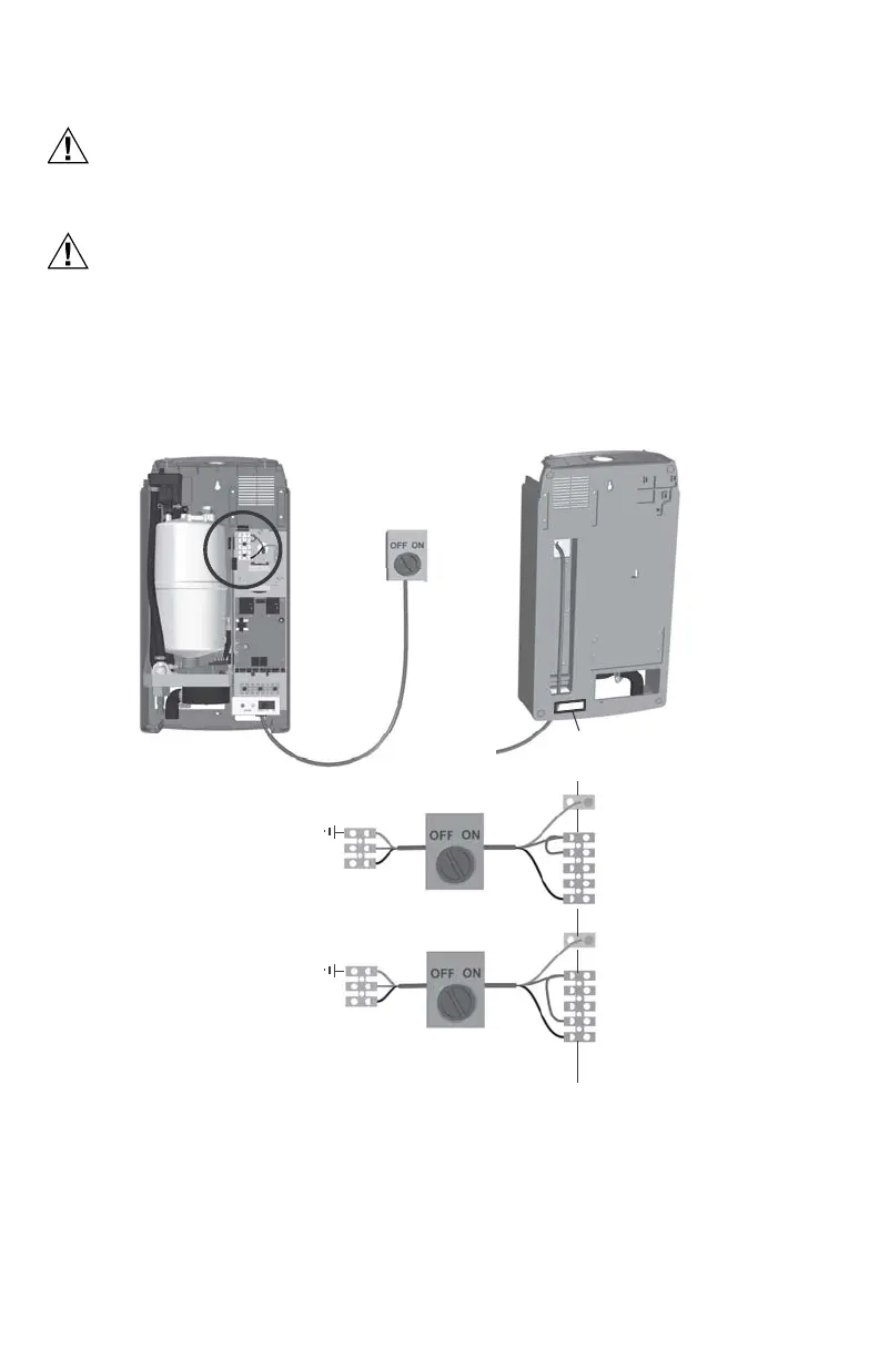
Fig. 3. Primary power connection.
NOTES:
— Honeywell requires the use of a GFI circuit on this device to protect the homeowner from electrical shock.
— When installed correctly, the green wire should be removed from the drain valve. The green wire comes
pre-installed from the factory to protect the homeowner in case of an improper installation or when it is not
possible to retrofit a GFI circuit.
— Ensure that adequate power is available to carry full humidifier amp draw as indicated on the specification
label.
— Do not use neutral wire as a ground; connect a dedicated ground to ground termination.
— All wiring to be in accordance with national and local electrical codes.
Hot
Hot
Ground
P
240
120
L1
Ground
E
X
T
I
N
T
240 VAC (1 PHASE)
120 VAC (1 PHASE)
Neutral
Hot
Ground
P
240
120
L1
Ground
Note:
(Optional)
(Optional)
Connect 120 VAC,
“Hot”, to L1
Note: Power wires can
also be routed through
opening in back of cabinet
 Loading...