1
General Information
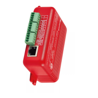
The HWF2-COM Commercial Fire Communicator (henceforth referred to as HWF2-COM) is a commercial Fire Alarm commu-
nicator that allows a Fire panel that previously reported by POTS to be upgraded to a system that uses the internet or cellular
means to connect to a central station.
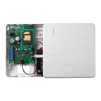
This dual path communicator connects directly to the primary and secondary communication ports of a Fire panel's Digital
Alarm Communicator Transmitter (DACT). It offers three selectable reporting paths which include; Cellular only, IP only, or IP
primary/cellular backup. In addition, the communicator’s power module (PowerBoost1) monitors and reports AC power loss,
and low battery conditions. All signals from the HWF2-COM communicator panel are delivered to Honeywell's AlarmNet Net-
work Control Center, which routes the information to the appropriate central station.
Package Contents
•
Red Fire Cabinet and Back Plate
•
Two Antennas, Mounting Adapters
and 50-ohm (9.5in) coaxial cable as-
semblies
•
• Mounting Rails (for above)
•
•
Wall Outlet Box (P/N K14358)
•
Transformer, 18VAC (N8167-1)
•
Compatible Fire Panels
The HWF2-COM is compatible with Fire Panels that use the Contact ID communication format as described in the SIA DC-05
Standard.
NOTE: The HWF2-COM ONLY supports ECP mode due to the communication with the built in DCID. The 4204, 2-4204, or
Zone modes are NOT a supported feature.
After completing the field installation, verify communications with the central station is successful by sending several events.
Also, get confirmation that these events were received.
Operation
The HWF2-COM replaces the fire panel's POTS communications path. When an event occurs, the fire panel goes off-hook to
dial the central station. The HWF2-COM detects the off-hook condition and provides the fire panel with a dial tone. When the
fire panel detects the dial tone, it begins dialing the central station. The HWF2-COM considers the three second period after
dialing as the number dialing has been completed. After the dialing is completed, the Dialer Capture Module returns a hand-
shake to the fire panel.
The fire panel then sends the contact ID reports to the HWF2-COM, which in turn sends a kiss-off after the report is success-
fully received from the fire panel. Within the HWF2-COM, the Dialer Capture Module sends the contact ID reports over the
ECP bus to the Communicator. When all the reports are sent, the fire panel goes on-hook. The HWF2-COM then transmits
the messages to the central station (either over the internet or the cellular network).
Installation
UL Compliance
To meet UL864/NFPA, ensure the following:
• HWF2-COM must be installed in accordance with NFPA (National Fire Protection Association) standards 70
and 72.
• HWF2-COM must be mounted in the same room and within 20 feet of the fire panel.
• The Telco line wiring and the Power Transformer wiring must be routed through conduit.
• HWF2-COM, and all equipment used for the IP connection (such as the router, hub, modem, etc.) shall be UL Listed,
must be powered from an un-switched branch circuit, and be provided with appropriate standby power.
• HWF2-COM must use a 7AH battery (not supplied) to provide 24-hour backup capability.
 Loading...