3
STEP 2 – Mount and Wire
• For UL compliant installations, refer to the topic on UL Compliance in this manual.
• For UL compliant installations, the Telco line wiring and the Power Transformer wiring must be routed
through conduit.
• For Dry/Indoor use only.
• Unless otherwise specified, use 18AWG.
• Additional cabinet wiring may be routed through conduit if desired.
This communicator comes partially assembled with all the components mounted except the external Antennas, LED Display
board, and PowerBoost1. To protect certain components on the PowerBoost1, it is shipped un-mounted. All internal wiring is
complete.
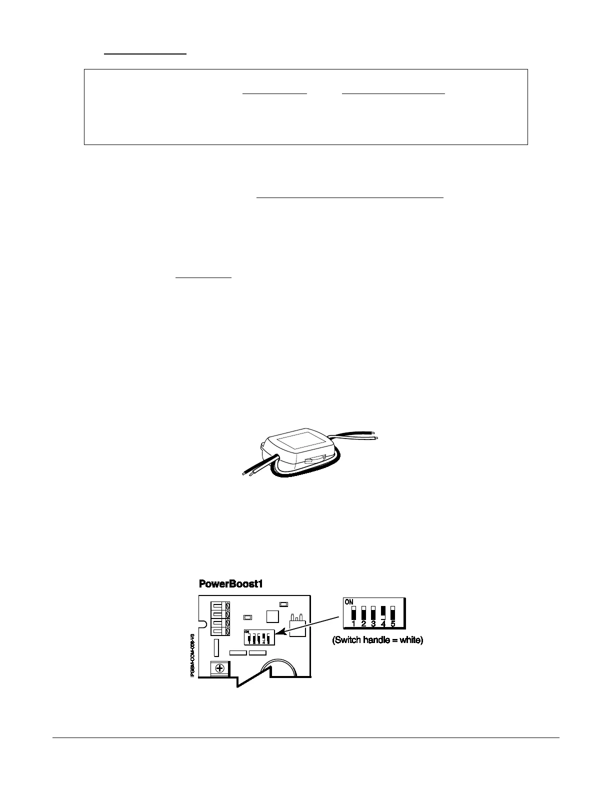
NOTE: Refer to the diagram on page 5, and to the Wiring Diagram on the inside of the back cover of this manual for wiring
and component identification.
1. Remove knockouts from cabinet to accommodate the power input wires, and wiring to the fire panel. Then mount the
cabinet securely to the wall using 4 screws or bolts. Use mounting screws or bolts that are suitable for the material
being anchored to.
2. Ensure the cabinet door lock is installed.
3. Install the two plastic mounting rails for the LED Display board. They simply snap into the back plate holes.
4. Connect the LED Display board to its connector, then slide the board into the mounting rails. (Yellow LED and Buzz-
er are on top.)
5. Carefully remove the packaging material that surrounds the PowerBoost1.
6. Mount the PowerBoost1 on the three unused standoffs. Use the two metal screws and lock washers to fasten the left
side of the circuit board. Ensure the lock washers are located between the circuit board and the head of the two met-
al screws. The right side of the board just snaps in place on the upper right standoff.
7. Mount the Wall Outlet Box to an un-switched facility power outlet and run a conduit to the cabinet.
8. In this step DO NOT plug the transformer in. Route wire (minimum 18AWG) from the transformer, through the
conduit and into the cabinet. Pass the wires through the Ferrite Filter, then loop the wires back through again making
a loop. Connect the wires to the PowerBoost1 AC terminals.
9. Connect and route 16AWG insulated wire from facility power ground (typically a cold water pipe) to the cabinet's
ground post. Ensure all ground connections are tight.
10. Connect the Ethernet cable and the Telco 1 and Telco 2 lines. If you choose to use an optional Cabinet Tamper
Switch (if the fire panel supports it) mount and wire it.
11. Verify the PowerBoost1 DIP switches are configured as shown below.
 Loading...