Do you have a question about the Honeywell HZ432 TrueZONE and is the answer not in the manual?
Voltage and transformer VA requirements for the panel.
Maximum VA draw specification for the zone panel.
Defines the type and gauge of wire for installation.
Acceptable non-condensing humidity range for operation.
Lists shipping and operating temperature ranges.
Refers to the physical dimensions diagram of the panel.
Confirms compliance with FCC Class B, Part 15 requirements.
Mounting the panel near HVAC equipment on a wall, stud, or truss.
Separating the cover and using the base to drill mounting holes.
Warning about electrical shock and equipment damage during wiring.
Installing thermostats and connecting their wires to the zone panel.
Installing dampers and connecting their wires to the zone panel.
Connecting the Discharge Air Temperature Sensor (DATS) to the panel.
Connecting the outdoor air temperature sensor to the panel.
Connecting HVAC equipment wires to the zone panel terminals.
Connecting wireless devices via ABCD terminals for the interface module.
Connecting the power transformer to the panel's power input.
Wiring diagram for a conventional system, illustrating connections.
Wiring diagram for a 2-heat/1-cool heat pump with electric auxiliary heat.
Wiring diagram for a 3-heat/2-cool heat pump with electric stage 3 heat.
Wiring diagram for dual-fuel with single-stage furnace and heat pump.
Wiring diagram for dual-fuel with two-stage furnace and heat pump.
Pressing the Mode button to activate the Config LED for setup.
Using Back/Next buttons to navigate menus and Adjust Setting.
Pressing Mode to set up for wireless device configuration.
Using the TAZ-4 panel for configurations with more than 4 zones.
Procedure to enter and use the Checkout mode for system verification.
The Honeywell HZ432 TrueZONE is a zone panel designed for professional installation in HVAC systems, enabling precise temperature control across multiple zones within a building. This device acts as the central control unit for a zoning system, coordinating the operation of thermostats, dampers, and HVAC equipment to deliver conditioned air only where and when it's needed.
The HZ432 TrueZONE panel manages up to four zones, allowing individual temperature settings for different areas of a home or commercial space. It supports various HVAC system types, including conventional (single-stage, multi-stage) and heat pump systems (2-heat/1-cool, 3-heat/2-cool, with electric auxiliary heat), as well as dual-fuel systems combining a furnace and a heat pump.
At its core, the HZ432 receives calls for heating or cooling from individual zone thermostats. Based on these calls, it intelligently controls the HVAC equipment (furnace, air conditioner, heat pump) and modulates zone dampers to direct airflow to the requesting zones. This zoning capability significantly enhances comfort by eliminating hot or cold spots and can lead to energy savings by avoiding conditioning unoccupied areas.
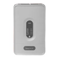
The panel features a clear LED display that communicates system and zone status at a glance. LEDs indicate the operational status of heat stages (HEAT 1, HEAT 2, 3), cool stages (COOL 1, COOL 2), purge cycles (PURGE), fan operation (FAN), and emergency heat mode (EM HEAT). Additionally, dedicated LEDs for each zone (ZONE 1, 2, 3, 4) provide visual feedback on damper status, showing whether a damper is open (solid green), closed (solid red), or experiencing a short circuit (blinking amber).
The HZ432 incorporates advanced control logic for optimal system performance. For heat pump and dual-fuel systems, it can integrate with an outdoor air temperature sensor (C7089U1006) to manage changeover points between heat pump and auxiliary/fossil fuel heat, optimizing efficiency based on ambient conditions. A discharge air temperature sensor (DATS C7735A1000) can also be connected to protect the HVAC equipment from extreme temperatures and to manage multistage operation.
The panel supports both wired and wireless thermostats. For wireless integration, a wireless adapter (THM4000R1000) can be connected, allowing for greater flexibility in thermostat placement. In systems requiring more than four zones, the HZ432 can be expanded using a TAZ-4 Add-A-Zone™ Control Panel, though a maximum of four zones can be configured when using wireless devices.
A key feature for variable-speed fan systems is the DS/BK terminal. When only one zone is calling for conditioning (or 25% on systems with more than four zones), this terminal de-energizes, reducing blower speed. This functionality, when connected to compatible HVAC equipment, can further enhance comfort by reducing noise and improving dehumidification.
Installation and configuration of the HZ432 TrueZONE panel are designed to be straightforward for professionals. The mounting process involves separating the panel cover from its base and using the base as a template to drill mounting holes. The panel can be mounted in any orientation, on a wall, stud, roof truss, or cold-air return, typically near the HVAC equipment. Wire management is facilitated by wire channels on the panel's sides and a wiring anchor for cable ties, ensuring a neat and organized installation.
Wiring diagrams are provided for various system types, including conventional, heat pump, and dual-fuel configurations, detailing connections for thermostats, dampers, HVAC equipment, outdoor air temperature sensors, discharge air temperature sensors, and transformers. Multiple dampers can be wired in parallel to a single zone.
The HZ432 offers both basic and advanced configuration options, accessible through the panel's interface using "Mode," "Back," "Next," and "Adjust Setting" buttons. The "Config" LED illuminates when in configuration mode. A flow chart guides installers through basic setup, covering system type (conventional or heat pump), number of cool and heat stages, RF enablement, and the number of zones installed.
Advanced configuration provides granular control over system parameters. This includes setting timers for stage 2 and 3 heat, purge cycles, and auto changeover delays. Installers can configure fan control during purge cycles, damper positions (unchanged or all open) during purge, and enable/disable DATS with adjustable high and low limits. Multistage DATS inhibit can be set to prevent downstaging near temperature limits.
For heat pump and dual-fuel systems, advanced settings allow for dual-fuel changeover based on outdoor temperature (OT) and multistage calls. OT temperature sensor enablement and lockout settings (Multistage OT Temp Lockout) are configurable, as well as the OT balance temperature for dual-fuel systems, which determines when the system switches from heat pump to fossil fuel. An OT trip point for multistage lockout can also be set. The LCD display contrast is adjustable for optimal viewing. Configuration settings can be saved or reloaded to default values.
Connecting wireless devices involves entering wireless mode via the "Mode" button (the "Wireless" LED lights up). The panel then prompts the installer to connect devices by pressing their respective connect buttons.
The HZ432 TrueZONE panel includes a comprehensive checkout mode to verify proper installation and operation. This mode is accessed by pressing the "Mode" button until the "Check out" LED lights up. The checkout process guides the installer through a series of tests using the "Adjust Setting" and "Next" buttons.
During checkout, the panel displays current outdoor temperature (OT SENSOR VAL) and discharge air temperature (DAT SENSOR VAL) readings. It then cycles through various operational tests:
Crucially, the checkout mode also allows for verification of thermostat wiring and wireless operation. By selecting "View Tstat1 inputs" (and for other zones), the panel displays the active terminals or indicates wireless thermostat operation. This helps confirm that thermostats are correctly communicating with the zone panel and that all wiring connections are sound.
The LED indicators on the panel itself serve as a continuous diagnostic tool during normal operation. Blinking LEDs for HEAT 1, HEAT 2, 3, COOL 1, and COOL 2 can indicate DATS high/low limit modes or stage lockouts due to DATS or OT. A blinking PURGE LED signals a DATS sensor failure, short, or open circuit. Blinking amber zone LEDs indicate a damper or thermostat short circuit, alerting to potential wiring issues or component failures.
The internal label on the HZ432 cover provides a quick reference for LED operation and configuration information, which can be helpful during troubleshooting. For users who prefer French or Spanish, translated labels are available.
In summary, the Honeywell HZ432 TrueZONE is a robust and flexible zoning solution designed for professional installation, offering comprehensive control, detailed configuration options, and built-in diagnostic features to ensure optimal comfort and energy efficiency in zoned HVAC systems.
| Zones | 4 |
|---|---|
| Power Supply | 24 VAC |
| LED Indicators | Yes |
| Auxiliary Heat Stages | 2 |
| Conventional Stages | 2 |
| Transformer | 40 VA |
| Maximum Current | 1A per zone |
| Wire Gauge | 18-22 AWG |
| Expandable | Yes |
| Wiring | 18-22 AWG |
| Humidity Range | 5% to 90% RH, non-condensing |
| Thermostat Compatibility | Standard 24 VAC thermostats |


