Copyright 2013 INNCOM by Honeywell
PN 292-100
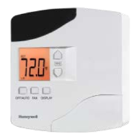
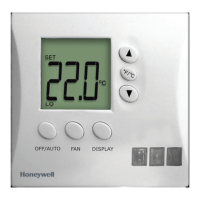
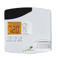
E528 RF Installation
• Typically only a wired door switch contact would be
required for this application (can also use wireless door
switch contact) or possibly a remote temperature sensor. In
this case, using the harness (P/N 62-1467), refer to low-
voltage communications connections table.
• Connect harness (P/N 62-1467) to H5 of e528.
Power and Actuator Connections
Refer to line voltage connections table
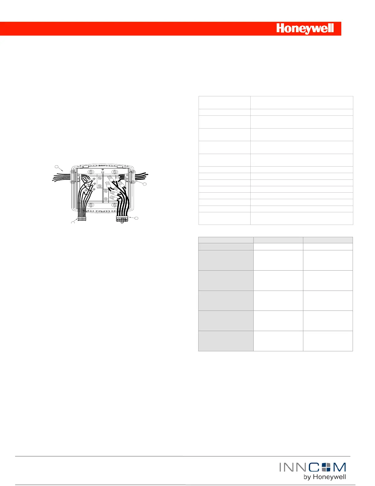
• Use wire nuts to connect the 10-pin Molex wiring harness to
the power and valve/fan control signal wires within the
electrical box. See pre defined commissioning document
which describes the specific wire connections for the
application
• Plug the pre-wired 10-pin connector into the female
receptacle at the back of the e528. Note: this will connect the
unit to the input power and relays to the loads.
Note: When using mixed voltage, voltage separation must be
maintained. Line voltage must reside in the right side of the gang
box. Low voltage must reside in the left side of the gang box.
• Hook the tabs at the top rear of the e528 housing into the
matching depressions at the top of the mounting plate and
rotate the bottom of the housing toward the wall until it
snaps into place on the mounting plate.
• Secure the housing to the mounting plate with the two small
screws removed in Step 1 of the Mounting section.
• Apply power to the e528 by closing the applicable supply
breaker. Verify that the e528 powers up. Values should
begin appearing on the LCD display.
Commissioning
The e528 digital thermostat requires configuration to work
effectively. The most basic configuration is “binding” the room to
the Room ID (usually the room number) to avoid cross
communication between devices. (For commissioning of complex
systems, please refer to the property specific commissioning
document). Room IDs are 5 digit numbers (X YY ZZ, with zeros
as placeholders where needed) ranging from 1 to 65535. To set
Room ID
• Enter Service Mode:
• Press and hold °F/°C
• Press and release OFF/AUTO
• Press and release DISPLAY
• Release °F/°C
• Go to rid (Room ID)
• Press OFF/AUTO. Default Room ID 65535 will scroll
• Set highest digit (0–6) using the UP/DOWN arrows. Press
DISPLAY
• Set middle 2 digits (0–99). Press DISPLAY
• Set lowest 2 digits (0-99). Press DISPLAY. The new number
will scroll across LCD. The e528 will return to the menu list
Technical Specifications
24 VAC at 50/60 Hz, 2.4 VA (e528-9xx)
100–277 VAC at 50/60 Hz, 2.4 VA (e528-8xx)
Triac Relay Contact
Rating
50m at minimum, 250m at maximum (e528-
4xx)
Thermostat
Measurement Range
Whole degree F, 0.5 °C (0.1 °F in test mode)
2 °F (1 °C) between heating and cooling
Toggle Button located on front display
41–149 °F (5–65 °C), 0–95% RH noncondensing
(HWD) 4.74.71.2in. (12012030mm)
UL listed #873, CAN/CSA C22.2 No. 24-93 File
#E202540/Part 15 of the FCC Rules
Load Specifications
-277VAC
-277VAC
-277VAC
-277VAC
-277VAC
FCC Statement
This device complies with part 15 of the FCC Rules. Operation is
subject to the following two conditions: (1) This device may not
cause harmful interference, and (2) this device must accept any
interference received, including interference that may cause
undesired operation.
Figure 7 E528.4G Connections
 Loading...