PN 292-100
Copyright 2013 INNCOM by Honeywell
E528.4G Headers and Connectors
Low-voltage Connections Table
(P/N 62-1467) Pinout
S5 Bus Data
Tx/Rx or IN 2
Line Voltage Connection Tables
24VAC Harness (INNCOM P/N 62-1464 R) Color Code, Pinout,
and Typical Functions
Medium Fan or Second Stage Heat
Cold Water Valve (FCU) or Compressor
Signal (Heat Pump)
Hot Water Valve (FCU) or Reversing Valve
(Heat Pump)
100-277VAC Harness (INNCOM P/N 62-1455) Color Code,
Pinout, and Typical Functions
Medium Fan or Second Stage Heat
Cold Water Valve (FCU) or Compressor Signal
(Heat Pump)
Hot Water Valve (FCU) or Reversing Valve
(Heat Pump)
E528.4G Retrofit
Installation
The e528.4G can be used to retrofit an
application where a legacy e528 was
used. Follow the procedure below:
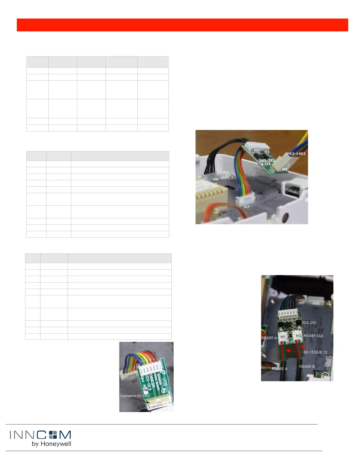
4G to 2G Standalone application:
with/without door switch input (no
backhaul network)
• Using the adapter (P/N 203-013) connect the harness from
the wall box (P/N 62-1462) previously connected to the
thermostat being replaced to H1 of the adapter.
• Connect the harness of 203-013 to H7 on e528.4G
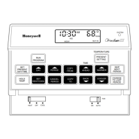
4G to 2G RS485 Networked Application: with or without door
switch input
• Using the adapter (P/N 203-251) connect the harness from
the wall box (P/N 62-1462) previously connected to the
thermostat being replaced) to H1 of the adapter.
• Connect the harness H3 (rainbow) of 203-251 to H7 of the
e528.4G
• Connect the harness H2 (Black) of 203-251 to H5 of the e528.4G
NOTE: Take care to not reverse the connections to the e528.4G!
E528 New Installation
Stand alone application with/without door switch input
• Using the harness (P/N 62-1467), make the appropriate wire
connections, then plug the harness into H7 of the e528. Refer
to low-voltage connections diagram.
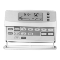
RS485 Networked Application with/without door switch input
• Using the harness (P/N 62-
1467), make the appropriate
wire connections, then plug
the harness into H7 of the
e528. Refer to low-voltage
connections diagram.
• Using the adapter (P/N 203-
250) and P/N 62-1532-B.12
cables, connect the RS485 in-
coming pair to two pin
header H1 and the out-going
pair going to the next
thermostat to header H3.
• Connect the harness of 203-
250 to H5 of the e528.
Figure 5 4G to 2G RS485 Networked Application