1
WIRING
The RDR-7000 is designed to be a drop-in replacement for existing Primus radar
systems; no wiring changes should be required in this scenario. Updated installations
using Real-Beam Maritime and/or 3D Volumetric Buffer may require additional wiring.
2
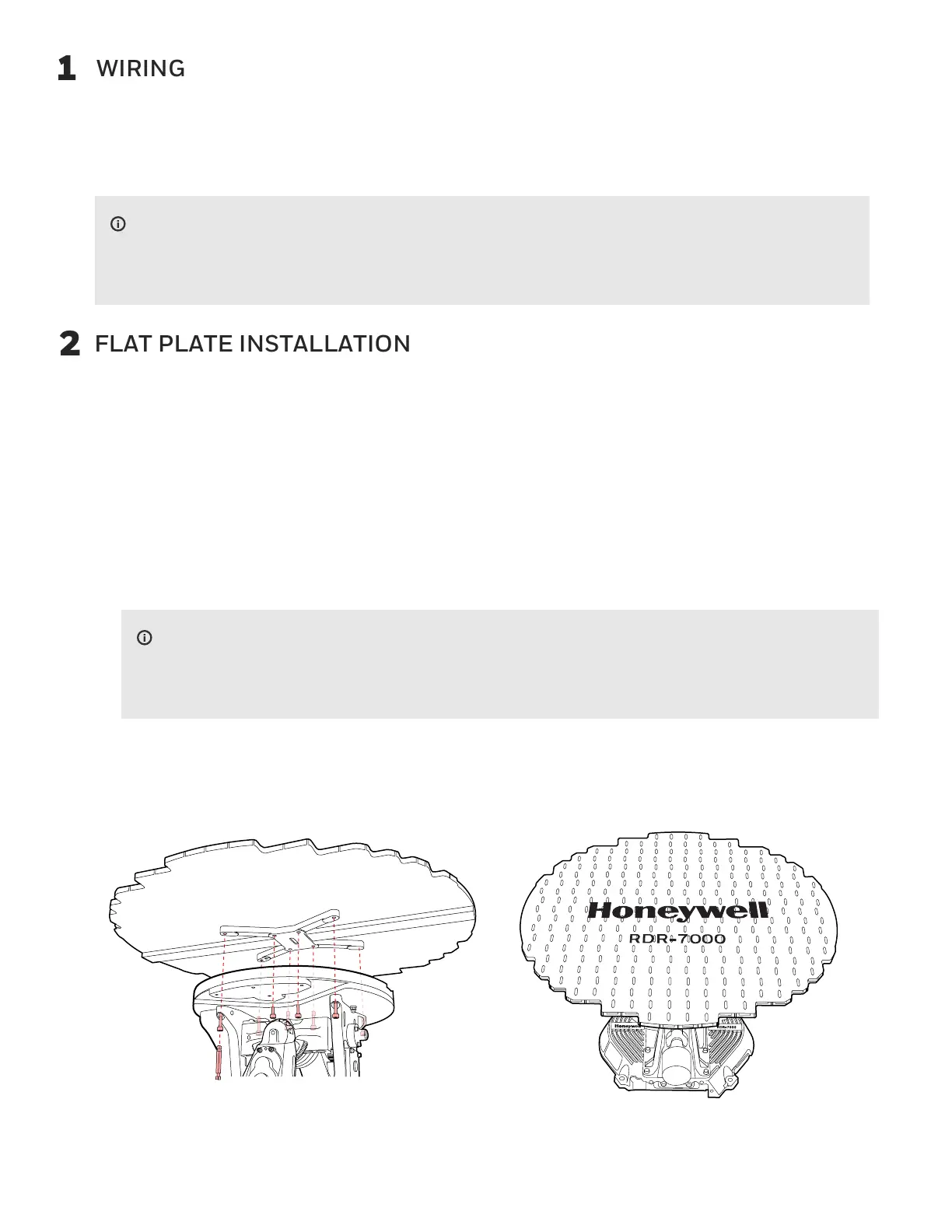
FLAT PLATE INSTALLATION
Remove the FP-7000 and/or ART-7000 from their storage containers (if applicable).
Carefully position the FP-7000 on the ART-7000.
Engage the four captive screws (outer screws) to attach the FP-7000 to the ART-7000.
Engage the four captive screws (inner screws).
Torque the screws to 23 to 25 in-lb (2.6 to 2.8 Nm), starting with the inner screws.
d.
e.
f.
g.
There will be approximately an eighth-inch gap between the antenna and the
ART-7000.
NOTE
It is highly recommended to use a 9/64 ball-end hex driver (included), that allows off
angle driving of hardware.
Visually inspect and remove any debris.c.
Remove the sticker from the back of the Flat Plate.
a.
b.
h.
Fig. 1. Flat Plate Installation
Refer to the full RDR-7000 installation manual and/or the appropriate STC for
instructions on how to complete the wiring.
NOTE
 Loading...