Do you have a question about the Honeywell BENDIX/KING RDR 2000 and is the answer not in the manual?
Introduces the manual's scope for the Bendix/King RDR 2000 Color Weather Radar System.
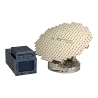
Describes the RDR 2000 system components: ART 2000, MFD, indicator, and configuration module.
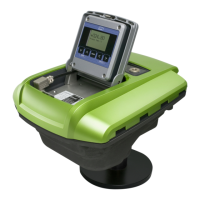
Details the ART 2000 unit, its components, and capabilities like stabilization.
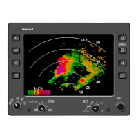
Describes the IN 182A display unit, its features, and video output.
Details AA2010V/H and AA2012V/H antenna types, polarization, and sizes.
Explains the CM 2000 module's role in storing configuration and calibration data.
Lists technical specifications for the radar system components.
Lists serial digital input and output labels for the ART 2000 system.
Provides specifications for ART 2000 transmitter, receiver, and operating parameters.
Lists the system components and accessories included with the RDR 2000.
Lists the part number for the ART 2000 unit for the RDR 2000 system.
Lists available configurations for the IN 182A indicator in the RDR 2000 system.
Lists available antenna configurations, including part numbers, sizes, and polarization.
States the CM 2000 module is included in the ART 2000 Installation Kit.
Lists part numbers and panel lighting for IN 182A installation kits.
Details essential accessories not provided with the RDR 2000 system.
Specifies the need for a vertical gyro or AHRS system for stabilization.
Details the requirement for quadraxial cable for ARINC 453 data transmission.
Explains the need for a converter for +14 Vdc aircraft systems to supply +28 Vdc.
Discusses radome requirements for signal transmissivity and aircraft configuration.
States the programmer kit is necessary for inputting data to the Configuration Module.
Lists optional equipment that can enhance the RDR 2000 system's functionality.
Describes how ART 2000 interfaces with EFIS systems, including control panel usage.
Details GC 360A interface with RDR 2000 and navigation systems.
Explains GC 362A interface for TCAS with the radar indicator.
Details GC 381A interface with KNS 81 RNAV and IN 182A indicator.
Lists installation kits required for CC 2024 unit with RDR 2000.
Describes CC 2024B for pilot selectable checklist presentation.
Explains IU 2023B interface with KNS 660 FMS and RDR 2000.
Specifies the requirement for an Aircraft Radio Station License to operate the system.
Provides general information for installing the RDR 2000 Color Weather Radar System.
Guides on carefully unpacking and visually inspecting equipment for damage.
Details installation procedures and considerations for the ART 2000 unit.
Discusses the importance of cooling for avionics reliability and lifespan.
Covers site selection for units, considering vibration, heat, RFI, and cable routing.
Provides general installation guidelines, precautions, and tips for the ART 2000 unit.
Details antenna attachment to the receiver-transmitter and dipswitch settings.
Explains mounting the ART 2000 unit behind a radome and surface preparation.
Describes installing the indicator in a tray, checking for magnetic interference.
Covers cable support, protection, grounding, and strain relief for reliable connections.
Guides through system configuration and calibration after installation.
Outlines configuring the system via the radar indicator, including antenna clearance check.
Details configuration for EFIS systems with older software versions.
Explains configuration for EFIS systems with newer software versions.
Guides through calibrating the stabilization system using various gyro inputs.
Outlines procedures to test system functionality before flight.
Verifies radar transmission and antenna operation through a test pattern.
Checks for interference between the radar and other aircraft electronic equipment.
Outlines preflight checks, including power, gyro erection, and test pattern display.
Describes procedures for testing system performance in flight.
Describes in-flight tests to verify pitch and roll stabilization accuracy.
Details checking the Vertical Profile feature and track cursor operation.
Provides a general overview of operating the RDR 2000 with the IN 182A indicator or EFIS.
Identifies and describes the controls and display features of the radar system.
Identifies controls and display features of the IN 182A indicator for RDR 2000.
Lists and explains error codes encountered during ART 2000 operation.
Details system functions, turn-on, mode selection, range, track, test, and turn-off procedures.