Do you have a question about the Honeywell Enraf SmartRadar FlexLine and is the answer not in the manual?
Explains how to use this installation guide for measurement systems.
Lists other documents relevant to installation, safety, and maintenance.
Information on registered trademarks used in the document.
Provides contact details for Honeywell Enraf for support and inquiries.
Overview of the SmartRadar FlexLine and importance of safety procedures.
Explains warning and caution symbols used throughout the document.
Details safety instructions, conformity, wireless compliance, and user requirements.
Guidelines for environmental conditions and disclaimer of liability.
Illustrates and describes the identification label on the device.
Outlines personal safety gear and general warnings for handling the device.
Guidelines for using appropriate tools, especially non-sparking ones.
Discusses safety precautions for hazardous and safe working environments.
Specifies the technical skills and training needed for installation.
Details electrical installation standards for hazardous areas (IEC, NEC).
Importance of proper grounding and checking resistance.
Details device compliance with various safety and communication regulations.
States compliance with FCC, R&TTE, and IC directives.
Specific installation requirements for microwave sealing and tank types.
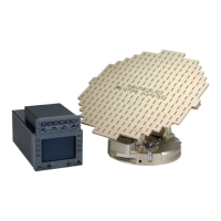
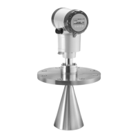
Identifies and illustrates the main components of the SmartRadar system.
Details the function and components of the SmartRadar FlexLine core unit.
Explains the function and components of the optional SmartView display and SmartConn box.
Lists various possible configurations and features of the device.
Safety precautions to be observed during the installation process.
Addresses electrostatic hazards and procedures for checking received components.
Guidelines for storing devices and prerequisites before installation.
Outlines the installation sequence and mechanical mounting.
Step-by-step guide to connect the device to the tank separator.
Instructions for mounting the communication antenna for the OneWireless option.
Steps for preparing the device when using the SmartConn option.
Steps for preparing the device when not using SmartConn.
Procedure for opening the main device cover, with cautionary notes.
Guidance on installing cable glands and plugs for SmartConn.
Instructions for installing glands and conduits without SmartConn.
Guidelines for using explosion proof (Ex-d) compound glands and conduits.
How to seal unused inlets and general electrical connection procedures.
Procedures and warnings for grounding the device.
Introduction to intrinsically safe connections and wiring separation.
Identifies the location of the terminal compartment and SmartConn terminals.
Details the intrinsically safe cabling entry and recommended cable colors.
Explains the terminal layout, zones (intrinsically safe/non-intrinsically safe), and labelling.
Connects non-intrinsically safe wiring to grey terminals and discusses cable combining.
Details DC and AC voltage requirements for the power supply.
Cable specs and topology for Enraf Fieldbus communication.
Describes the topology for connecting multiple devices on the field bus line.
Cable specifications and topology for EIA 485 communication.
Illustrates the parallel connection topology for EIA 485 communication.
Cable specifications and topology for EIA 232 point-to-point communication.
Shows the point-to-point topology for EIA 232 communication.
Usage of hardware relay outputs for alarms and remote device operation.
Detailed parameters for FII-DO relay outputs (Ry1-Ry4).
Parameters for FII-DO overfill protection relay outputs.
Cable specifications and parameters for HCI-HAO (4-20 mA) signals.
Connects intrinsically safe wiring to blue terminals.
Cable specs and parameters for VITO temperature and water bottom measurement.
Topology for VITO connection (one device).
Cable specs and parameters for HART communication.
Topology for HART connection, specifying maximum devices.
Cable specs and parameters for FII-RTD temperature measurements.
Parameters for RTD 4-wire connection.
Parameters for RTD 3-wire connection.
Parameters for MPT-MRT connection.
Wiring terminal labelling for standalone SmartView displays.
Final steps for completing installation with SmartConn.
Final steps for completing installation without SmartConn.
Instructions for closing the device cover safely.
Steps to replace the top cover after installation.
Provides the physical dimensions and weight of the SmartRadar and SmartConn.
| Type | Radar Level Transmitter |
|---|---|
| Power Supply | 24 V DC |
| Output Signal | 4-20 mA |
| Technology | FMCW (Frequency Modulated Continuous Wave) |
| Accuracy | ±1 mm |
| Process Temperature | -40 °C to +150 °C (-40 °F to +302 °F) |
| Process Pressure | Up to 40 bar |
| Communication Protocols | HART, Modbus, Foundation Fieldbus |
| Process connection | Flanged or threaded |
| Operating temperature | -40 to 80°C |
| Ingress Protection | IP66/IP67 |
| Approvals | ATEX, IECEx, FM |
| Housing Material | Aluminum, Stainless Steel |
| Antenna Material | PTFE, Stainless Steel |
| Measurement Principle | Non-contact radar level measurement |