BENDIX/KING RDR 2000
Page 2-4 00643I05.TDC Rev 7, July/2002
A. Lay the antenna on a clean, smooth, table top, with mounting holes and port opening fac-
ing up.
CAUTION
AVOID DENTING OR SCRATCHING THE ANTEN-
NA RADIATING SURFACE.
B. Place the receiver-transmitter on the antenna with the holes aligned. Attach the antenna
plate with the screws (089-06494-0005) provided with the Honeywell Installation Kit.
C. Carefully pivot the base of the receiver-transmitter to one side and tighten the exposed
screws. Pivot the unit to the other side and tighten the remaining screws.
D. Access the DIP switches through the access port on the ART 2000 and set to the appro-
priate antenna (see Table 2-1). The switch is ON when pushed toward the center of the
ART 2000.
1. For a 10" antenna, set switch #4 to the ON position and switch #5 to the ON
position.
2. For a 12" antenna, set switch #4 to the OFF position and switch #5 to the ON
position.
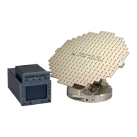
2.3.3.2 Installation of ART 2000 Antenna/Receiver/Transmitter
The Antenna/Receiver/Transmitter is designed for mounting to the forward bulkhead in the nose
section or a wing pod of an aircraft, behind a radome fabricated for the operating frequency of the
radar system. Check all mounting surfaces before mounting the ART 2000 to the bulkhead to en-
sure a good electrical bond to the airframe.
After base metal has been exposed, treat the surface with Alumiprep #33 (016-01127-0000). Alu-
miprep #33 removes light deposits of oil and grease, mill markings and corrosion products as well
as natural oxides.
After the surface is dry, treat it with Alodine #1001 (016-01128-0000). Alodine #1001 chemically
stabilizes aluminum, provides increased corrosion resistance and does not change the appear-
ance of the aluminum.
Both Alumiprep and Alodine should be wiped off with a clean damp rag to remove any excess.
The total space required for the radar antenna can be determined from the dimensional informa-
tion contained on the ART 2000 Outline and Mounting Drawing, figures 2-29, and 2-30.
CAUTION
BE CERTAIN THAT THE ANTENNA IS FREE TO
MOVE IN AZIMUTH PRIOR TO APPLYING POW-
ER.
The forward bulkhead should contain a bolt hole (1/4" dia.) pattern which agrees with the mounting
hole pattern of the ART 2000. See figure 2-29. Due to the limited area for bolt heads, socket-
head cap screws should be used for mounting.
For installations where the cable must come through the bulkhead behind the base of the
ART 2000 (such as in a Wing Pod), the cable may be flattened to pass behind the base. Add
1/4" diameter (.071" thick) flat washers or similar spacers between the ART 2000 base isolators
and the aircraft bulkhead to increase clearance for the flattened cable.
To obtain optional stabilization analog inputs for the radar, the pitch, roll and gyro excitation sig-
nals must be connected as shown in the figure 2-41, Analog Stabilization Interconnect. See figure
2-42 for AHRS Stabilization Interconnect.
No connections are required if the stabilization inputs are not desired.