BENDIX/KING RDR 2000
Page 2-30 00643I05.TDC Rev 7, July/2002
7. Proceed to Step Q.
Q. AHRS ARINC 429 ROLL OFFSET
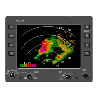
1. Adjust the GAIN knob for a GAIN POT setting between -7.0 and -9.0 (see figure 2-
10). An 07 should be displayed in the AZIMUTH COUNT field (see table 2-2).
2. Check that the tilt table is set for 0
°
roll.
3. Adjust the TILT SETTING between 5 and 10 UP to increment the ROLL ANGLE
field to 0.0 ± 1.0
°
(adjusting the TILT SETTING between 5 and 10 DOWN will dec-
rement the numbers). Upon reaching 0
°
± 1.0
°
, quickly adjust the TILT SETTING
to above 10 to lock in the setting. See figure 2-11.
4. Set the tilt table to 10
°
roll right. The value should be 10.0R ± 1.0
°
. If the value is
out of range, repeat Steps 1, 2, and 3 of this section.
5. Set the tilt table to 10
°
roll left. The value should be 10.0L ± 1.0
°
. If the value is out
of range, repeat Steps 1, 2, 3, and 4 of this section.
6. Set the tilt table to 0
°
roll. The value should be 0.0 ± 1.0
°
.
7. Proceed to Step R.
R. SAVE CONFIGURATION
1. Adjust the GAIN knob for a GAIN POT setting between -3.5 and -5.5 (see figure 2-
10). An 08 should be displayed in the AZIMUTH COUNT field (see table 2-2).
2. Set the TILT SETTING to 15.0D. The fault fields will flash indicating the save pro-
cedure is beginning. If the save procedure is successful, the GYRO fault will dis-
appear and the azimuth count field will step.
3. If the GYRO remains unchanged, TILT to 0
°
then repeat Step 2.
2.4.4.3 Stabilization Calibration with EFIS 40/50 Software Level 09 or Above
The following procedure assumes that both analog and ARINC 429 stabilization inputs are
present. If one or the other inputs are not available, this situation will be annunciated on the ap-
propriate page. No adjustments can be made on a page displaying no inputs available.
The following procedures are accomplished by utilizing the controls on the EFIS Control Panel and
the Radar Control Panel.
A. Set the radar function selector to the TEST position. Press and hold the TST/REF button.
This places the EFIS system in self test mode.
B. When the display shows SELF TEST PASS, simultaneously press the HSI and ARC but-
tons. This must be done within five seconds of SELF TEST PASS being displayed. The
EFS 40/50 MAINTENANCE page should now be displayed. See figure 2-6A.
C. Press the RANGE DOWN button to display the EFIS MAINT FUNCTION page. See figure
2-6B.