BENDIX/KING RDR 2000
Rev 7, July/2002 00643I05.TDC Page 1-11
1.5 ACCESSORIES REQUIRED, BUT NOT SUPPLIED
1.5.1 STABILIZATION REQUIREMENTS
A vertical gyro (see Analog Stabilization Inputs drawing) or AHRS system (see AHRS Stabilization
Inputs drawing) must be used to fully stabilize the RDR 2000 Radar System. The gyro provides
excitation and pitch and roll signals for the stabilization circuits in the ART 2000. It is recommend-
ed that isolation transformers be used for pitch and roll inputs when the ART 2000 is installed with
a gyro that does not have isolated outputs for radar stabilization. Isolation Transformer P/N (019-
05098-0001)is the recommended part.
1.5.2 QUADRAXIAL CABLE
Quadraxial cable (024-00064-0000) shield is required for transmission of ARINC 453 data from
the ART 2000 to the IN 182A. Refer to the System Interconnect Drawings for details. A specific
length must be determined prior to placing an order.
1.5.3 +14/28 VDC CONVERTER
A +14/28 Vdc converter (068-01016-0003) is required when the RDR 2000 is installed in a +14
Vdc aircraft system to supply +28 Vdc to the radar. Refer to installation manual P/N 006-00578-
0000 for details.
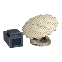
1.5.4 RADOME
Radome kits and installation directions must be ordered directly from radome manufacturers or
supplied by the aircraft manufacturer. The radome provides a radar window for the radar signal
while retaining the original nose configuration of the aircraft.
The ART 2000 is mounted directly behind the radome. The radome must have a transmissivity of
90% or better for proper radar operation.
1.5.5 CONFIGURATION MODULE PROGRAMMER KIT
The KPA 900 Configuration Module Programmer Kit (P/N 050-03311-0000), is necessary to input
configuration data to the Configuration Module before the module is installed in a radar indicator
only (or EFIS 40/50 with software level 08 or lower and EFS 10) installation.
1.6 OPTIONAL ACCESSORIES
1.6.1 INSTALLATIONS WITH EFIS
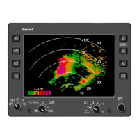
When the ART 2000 is installed in the EFS 40/50 system, the KMD 540 or IN 182A Radar Indicator
does not have to be installed. In this case, the CP 466A Radar Control Panel is used to operate
the weather radar. When the ART 2000 is to be installed with the EFS-10 system the IN 182A
Radar Indicator is not required. However, either the CP 113N or the CP 123J Radar Control Pan-
els must be installed to control the radar.