BENDIX/KING RDR 2000
Rev 7, July/2002 00643I05.TDC Page 2-41
As a result of these factors, the stabilization system accuracy can vary up to ±10% of the pitch or
roll angle of the aircraft. This accuracy can be tested in flight by performing the following proce-
dure.
A. Fly the aircraft being tested to 6,000 feet AGL or to the aircraft’s normal cruise altitude,
whichever is most convenient.
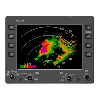
B. Select the MAP mode and set range on radar indicator to 20 miles. Set manual GAIN con-
trol to maximum gain (full clockwise on gain knob).
C. While flying with wings level (0
°
roll) and minimum pitch to maintain altitude, adjust the an-
tenna tilt control on the radar indicator to obtain the video pattern shown in figure 2-21.
Then note the antenna tilt control setting.
This tilt angle should be about 2.0
°
down, but will vary with aircraft type, antenna size and al-
titude. The terrain band (for open and dry land) should be displayed above the range mark as
shown.
If the inner ring of video is not parallel to the range mark (figure 2-21), the error is caused by
mechanical displacement of the antenna about the roll axis of the aircraft. Follow the applica-
ble stabilization calibration procedures in Section 2.4.4 to obtain the proper display.
NOTE
Minor corrections may be made with the Roll Trim
Adjustment on the Radar Indicator/Controller.
D. Roll the aircraft gradually 20
°
to the right (the gentle maneuver will minimize gyro preces-
sion). For perfect stabilization, the terrain band shown in figure 2-21 should not change.
E. If the terrain band changes in Step E to a display as shown in figures 2-23A or 2-23B the
roll gain must be increased or decreased, as indicated by the illustration. Adjust the roll
gain accordingly.
F. Make a gentle 20
°
left turn and repeat the observations in Step E.
G. If the roll stabilization is inoperative, an image similar to figure 2-22 will be observed.
H. With wings level, pitch the aircraft up 5
°
. The display should appear as in figure 2-21. If
the display appears as in figure 2-24A or 2-24B, the pitch gain is set too high or too low,
as indicated by the illustration. Adjust the pitch gain accordingly.
I. If the center of the display changes by exactly 5
°
in Step I, the pitch circuit is inoperative.
2.6.2 VERTICAL PROFILE CHECK (if system is so equipped)
A. Press the VP button with the system in Wx or WxA mode.
B. A short period of time will elapse before the vertical picture is "painted". This is because
the radar continues to scan normally after the VP is pressed, until it reaches the selected
azimuth position.
C. Adjust the TRACK cursor with the TRACK buttons to obtain a vertical "slice" at the position
the TRACK cursor is positioned.
D. Push the Wx/WxA button to return to horizontal weather scan. A TRACK line will remain
on the screen for 15 seconds to indicate the location of the last profiling azimuth angle.