BENDIX/KING RDR 2000
Rev 7, July/2002 00643I05.TDC Page 2-21
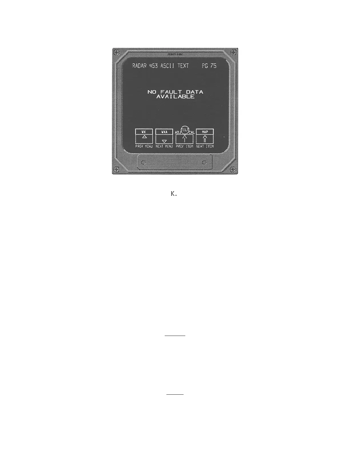
FIGURE 2-9 DIAGNOSTICS MENUS FOR SYSTEM CHECK (Cont’d)
2.4.4 STABILIZATION CALIBRATION
Before stabilization can be calibrated, the radar stabilization source must be removed from the air-
craft and mounted on a tilt table. Mount the gyro on a suitable tilt table at 0
°
pitch and 0
°
roll. Put
the radar into calibration mode. Rock the gyro on its pitch axis approximately 5
°
up to 5
°
down.
Repeat on the roll axis. (This causes the radar to look for the lowest AC voltage the gyro is pro-
ducing.)
When aligning the ART 2000 with the KI-256 Gyro, vibrate the gyro during the alignment. (This
may be accomplished by simply rolling a screwdriver across the tilt table.)
NOTE
It is recommended that isolation transformers be used for
pitch and roll inputs when the ART 2000 is installed with a
gyro that does not have isolated outputs for radar stabilization.
Isolation Transformer P/N 019-05098-0001 is the recom-
mended part.
NOTE
When the radar is in the test mode, stab off will be
displayed in the upper left corner of the display.
 Loading...