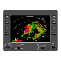
BENDIX/KING RDR 2000
Rev 7, July/2002 00643I05.TDC Page 2-5
Use a light lubricant on the self tapping screw for the connector hood. This allows easier installa-
tion of the screw.
For proper operation of the radar in stabilized flight, the unit mounting surface should be perpen-
dicular to the level-attitude flight path. This may be checked with a spirit level while the gyro is
indicating level flight.
If the bulkhead mounting surface is not accurate, the ART 2000 may be mounted in a correct at-
titude by placing shims between the unit and the bulkhead.
For example, if the bulkhead was tilted back 1/2
°
, the unit could be corrected by placing 1/16-inch
shims between the unit and the bulkhead at the top only (for 1
°
add 1/8-inch shims, etc.).
A. Ventilation
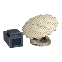
The ART 2000 is designed to operate in the unpressurized nose section of the aircraft and
ventilation is not important.
B. Pressurization
The antenna is designed to operate within ambient air pressures ranging from sea level (and
below) to an altitude of 55,000 feet, without pressurization.
The ART 2000 is installed in the nose section of the aircraft or wing pod, which is not normally
pressurized.
C. Orientation
The ART 2000 must be mounted to within 1
°
of level in both the vertical and horizontal planes
and near the longitudinal (fore-aft) centerline of aircraft.
The ART may also be mounted inverted if necessary. This may be desirable if the ART 2000
is being installed in an existing RDS system. Unit orientation will be noted when performing
the antenna configuration.
D. Water and Humidity
The installer must insure that the radome is properly sealed against water ingression and ac-
cumulation of condensation.
E. Radome
To allow the most satisfactory radar beam radiation, the nose section (radome) in front of the
ART 2000 should be fabricated for X-band signals.
A radome having less than 90% transmissivity, at all incidence angles defined by the scan and
tilt coverage, will result in degradation of system performance and should not be used. A good
radome will have a transmissivity greater than 90%.
When the radome is installed it should allow the widest possible angle of useful beam radiation
(120
°
, 60
°
to each side of aircraft heading). Radar range, in terms of that attainable without a
radome, is equal to the square of the radome transmissivity percentage.
Follow good radome grounding practices to guard against static charges building up and af-
fecting the performance of the RDR 2000 system.
If there is doubt of the quality of radome material, a flight test should be performed to evaluate
the performance over the anticipated ranges and tilt angles that will be required for that type
of aircraft. See FAA Advisory Circular 43-14 for additional radome information.
2.3.3.3 KMD 540 Installation
Please refer to the KMD 550/850 Multi-function Display System Installation Manual (P/N 006-
10608-XXXX) for KMD 540 Installation.