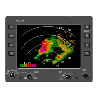
BENDIX/KING RDR 2000
Page 2-2 00643I05.TDC Rev 7, July/2002
NOTE
When the transmitter is on, a magnetic field is creat-
ed by the heavy DC current drawn. The indicator
contains a magnetic shield that encloses the bulb of
the cathode ray tube to eliminate this type of interfer-
ence.
The RDR 2000 system operates primarily from the aircraft’s 28 Vdc power system. Refer to the
System Interconnect Diagrams. Both the ART 2000 and the IN 182A/812A in the system are op-
erated from the +28 Vdc aircraft power through their own circuit breaker. The KMD 540 will oper-
ate with an input voltage of 10 to 33 VDC; however, front panel lighting must be +5 VDC, 5 VAC,
+14 VDC, or +28 VDC depending on the aircraft lighting bus.
Figure 2-43 is the Outline and Mounting Drawing for the IN 182A. Cable assemblies will be fabri-
cated by the installing agency. Installation kits containing the mounting hardware and the unit con-
nectors for various systems are available. Consult paragraph 1.4 in Section 1 of this manual.
2.3.3 INSTALLATION
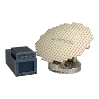
The ART 2000 is a high power digital weather radar. Precautionary measures are necessary dur-
ing the installation and operation of this unit to avoid damaging it and/or degrading its perfor-
mance.
Precautionary measures:
The ART 2000 is specified to have a operating VSWR of up to 2:1. To prevent loss of performance,
the following precautions are recommended:
Lightning diverter strips installed on the bottom of the radome may cause problems with the
ART 2000 Contact Honeywell Business and General Aviation Customer Service Product Sup-
port before operating the ART 2000.
Avoid using lead or metallic flake paints on the radome.
Avoid operating the radar near steel buildings.
Installation Guidelines:
Gyro accuracy and calibration at installation are key elements of radar stabilization. Each gyro is
unique, so the ART 2000 stabilization calibration procedure has been designed to compensate for
a wide variety of gyro sources.
Installation tips:
• Pin 8 on the IN182A must be grounded when wired to the ART 2000 as side 1.
• The ART 2000 minimum equipment list is addressed in its Installation Manual P/N 066-
00643-0005
The ART 2000 has a dipswitch with eight settings for factory and installation functions. The
dipswitch MUST have the proper configuration for the radar to perform properly. Note that a set-
ting is on when it is positioned facing the center of the unit.