3
RADAR INSTALLATION
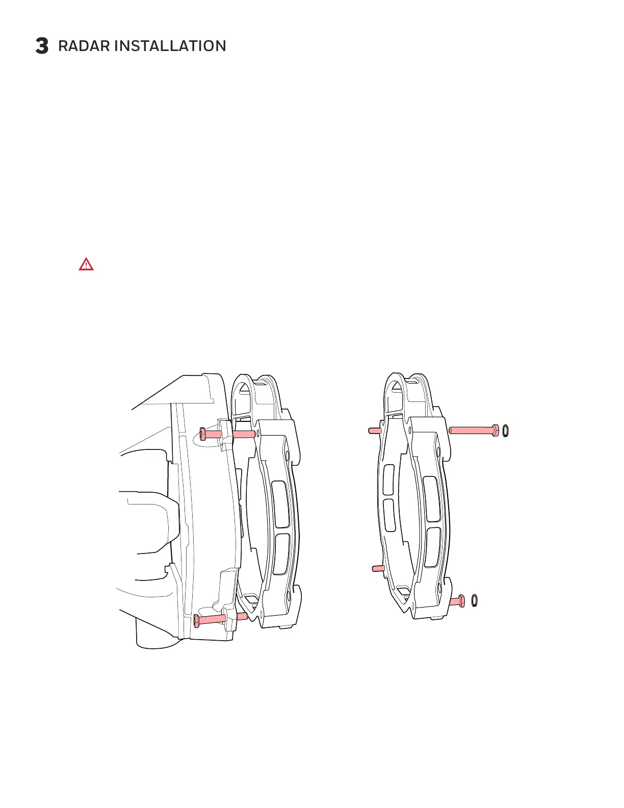
Move the ART-7000 to the open radome.
For 18” antenna systems, align the 1-inch spacer behind the ART-7000, if necessary.
Hold the assembled unit along with the 1-inch spacer firmly in position on the nose
bulkhead mounting plate and attach with four through bolts.
a.
b.
c.
• Attach the top bolts first.
• Torque the screws to 30 to 35 in-lb.
Electrical grounding is required. If not attached to a bonding surface, add a
ground strap.
Attach the aircraft electrical connector to the ART-7000 and tighten the
captive screws.
Visually inspect the installation. Remove any debris from the area.
Ensure that there is no constraint on the full range of motion of the antenna
(cables, other equipment, etc.)
Do not touch the electrical pins of the connectors. Damage can occur to
the ESDS components.
Fig. 2. Radar Installation
OR
 Loading...