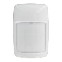
Do you have a question about the Honeywell IS-215T and is the answer not in the manual?
Guidelines for selecting the optimal mounting location, including height and environmental factors.
Steps for mounting the sensor housing, including wiring and securing it to a wall or corner.
Instructions for connecting wires, specifying gauge size and emphasizing polarity for proper installation.
Details on configuring sensor sensitivity using SW2 switch for different pulse count settings.
Guidance on how to perform a walk-test to verify sensor functionality and sensitivity levels.
Details on the sensor's detection range and required power supply voltage and current.
Information on the sensor's detection zones and suitable operating temperature and humidity.
Physical specifications including the sensor's dimensions and weight.
List of certifications and compliance standards the sensor meets.
Diagrams illustrating the sensor's detection coverage from a top-down perspective.
Diagrams showing the sensor's detection coverage from a side-view perspective.
Mandatory conditions for UL certified installations, including power supply requirements.
Information regarding suitability for connection to EN 60950 Class II Limited Power Source.
| Detection Method | Passive Infrared |
|---|---|
| Power Supply/Voltage Range | 9-16VDC |
| Current Draw (standby) | 15 mA |
| Alarm Current | 25 mA |
| Color | White |
| Detection Range/Coverage Area | 15m diameter at 2.4m mounting height |
| Operating Temperature | -10°C to +55°C (14°F to 131°F) |
| Alarm Output | Normally Open (NO) or Normally Closed (NC) |
| Tamper Switch | N.C. 28VDC 0.15A |
| Operating Humidity | 95% RH max. non condensing |
| Certifications | UL |
| Weight | 227 g |




 Loading...