EasyManuals Logo

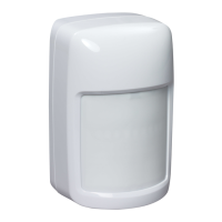
Honeywell IS335 User Manual

Honeywell IS335
4 pages
To Next Page IconTo Next Page
To Previous Page IconTo Previous Page
Page #2 background imageLoading...
Page #2 background image
3
Mount the Sensor
IS335-013-V0
A
B
B
B
A
B
A
B
*
#6 x 1"
(3.5 mm x 25 mm)
IS312QIG-005-V0
*Not included
[A] = Wall mounting holes.
[B] = Corner mounting holes.
4
R
oute Wires
IS335-006-V0
Shielded
Cable
22-20 AWG
(0.32-0.52mm )
2
Reinstall Circuit Board
IS335-012-V0
Push
Down
6
Connect Wires / Set Pet Immunity (PI) Jumpers
Assemble Front Cover
#6 x 1"
(3.5mm x 25mm)
CNC V+V-T1T2
1
2
3
Pet Immunity
*Factory default
LED
Always
Enabled
IS335-007-V0
Disabled
*Enabled
Alarm 90 mA, 15 VDC
Power 12 mA max, 9-15 VDC
NC V
-
V
+
C
Ground +12V
Zone
#
Zone
COM
Panel
Sensor
For Residential use with
compatible panels,
minimally Listed to UL 1023,
that produce visual and/or
audible troubles/alarms

Questions and Answers:

Question and Answer IconNeed help?

Do you have a question about the Honeywell IS335 and is the answer not in the manual?

Honeywell IS335 Specifications

General IconGeneral
BrandHoneywell
ModelIS335
CategorySecurity System
LanguageEnglish

Related product manuals