GB-5
Wiring
WARNING
Electric shocks can be fatal!
– Before working on possible live components,
ensure the unit is disconnected from the power
supply.
– Incorrect wiring may result in unsafe states and
the destruction of the tightness control, the au-
tomatic burner control unit or the valves.
– Do not reverse L1 (+) and N (–).
– Cable cross-sections must be designed for the
current rating of the selected external fuse.
– The valve outputs on the automatic burner con-
trol unit connected to the TC must be safe-
guarded by an external slow-acting fuse of max.
5 A (e.g. in the automatic burner control unit).
▷ Wiring to EN60204-1.
▷
Use connection terminals with a cable cross-
section of max. 2.5mm
2
.
▷
Conductors which have not been connected
(spare conductors) must be insulated at their
ends.
▷ Do not set the remote reset so that it operates
(automatically) in cycles.
▷
The data on the type label must comply with the
mains voltage.
▷
Length of the connection cable, see page 10
(Technical data).
CAUTION
Please observe the following to ensure that the unit
is not damaged during operation:
– Avoid voltage and current peaks! It is recommen-
ded to equip connected valves with a protective
circuit in accordance with the manufacturer’s
instructions.
Disconnect the system from the electrical power
supply.
Shut off the gas supply.
▷
Before opening the unit, the fitter should ground
himself.
Open the housing cover of the TC.
Preparing the wiring
24
3
5
6
7 Secure used cable glands. Tightening torque:
max. 3.5 Nm.
▷ Unused cable glands are to remain closed with
a plug. Otherwise, dirt or moisture can penetrate
the housing.
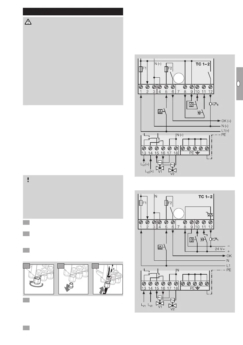
8 Wire as shown on the connection diagram.
▷
For PE wire connection, 5 PE terminals are avail-
able for forwarding. They are designed as dis-
tributor terminals, e.g. to connect the PE wires
of the valves to the system PE (connection to the
system PE must be carried out/wired by the user).
Connection diagram for TC, TC
Mains voltage and control voltage:
24VDC/120VAC/230VAC
Mains voltage: 120VAC/230VAC,
control voltage: 24VDC

 Loading...


