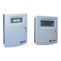
Fire Alarm Control Panel LT
-32 / LT-159
-168.2-EN / 07.2022
Honeywell
MORLEY IAS Fire Systems
Technical changes reserved!
© 2022 Honeywell International Inc.
Morley LT-32 Morley LT-159 Panel Installation - Three Steps Process Cable Entries Field Cable Entry
STEP 1
According to the figure, mark
the required hole on the wall.
STEP 2
All fixing point must be used.
Use 50 mm long x 5 mm diameter
screws to secure the backbox on the
• Upper and lower cable entry for 15 mm gland
• Side entry: 3 on each side (21 x 21 mm easy access)
• Central entry prepared for 60 mm universal flush box
Remove the keyholes and pass
the cables through them.
Power supply and batteries are required for commissioning!
Align the screws on the cover with the keyhole on the back box and lock
the cover onto the backbox.
System Setup and Cabling
Alarm and Fault Relay
Move the Jumper to Setup NO or
NC relay functionality.
Sounder circuit
End of line diode cathode marker on
positive terminal.
LT-32 Ref. Description LT-159 Ref. Description
1 Fault NO/NC
1 Fault NO/NC
2
Fault C
2
Fault C
3
Alarm NO/NC
3
Alarm NO/NC
4 Alarm C 4 Alarm C
5
Loop A +
5
Loop A +
6
Loop A -
6
Loop A -
7 Sounder 2 + 7 Loop B +
8
Sounder 2 -
8
9
Sounder 1 +
9
Sounder 1 +
10 Sounder 1 - 10 Sounder 1 -
11 Power +
11
Power +
12
Power -
12
Power -
Panel Connection
Highlighted the differences between panel LT-32 and LT-159.
Battery Connection
Batteries connected in two rows
with polarity as shown.
Additional and updated Informations
The described features, specifications and product related informations in this manual correspond to the date of issue (refer to date on the front page) and may differ due to modifications and/or amended Standards and
Regulations of the System design, Installation and Commissioning.
For further Informations refer to documentation M-168.1-SERIE-LT-EN.