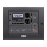
Do you have a question about the Honeywell Notifier LCD6000N and is the answer not in the manual?
Safety guidelines for installation, environment, ESD, power, and maintenance to prevent damage.
Details on microprocessor, LCD display, keyboard, serial interface, voltage, connection, and mechanical specifications.
Specifies dimensions and mounting considerations for wall installation, including screw size and placement advice.
Explains the meaning of ALARM (Red), FAULT (Yellow), and TACITATION (Yellow) LED indicators.
Describes the screen display in normal operation, including icon status and counter areas.
How to select and assign a peripheral number (address) to the LCD6000N.
Overview of available local programming menu options like buzzer volume, LED test, and LCD test.
Details on accessing and using Level 2 and Level 3A passwords for acknowledgement and reset operations.
Instructions for performing LED Test and LCD Test functions on the panel.
Explains 'Multi-Point' (daisy chain) configuration, wiring, EOL resistors, and maximum length for RS485 communication.
Guidelines for connecting RS485 circuits, emphasizing proper handling of ground wires and shield connections.
Diagram showing the layout of the LCD6000N board, identifying key components like Buzzer and CN1 Terminal block.
Description of terminals on CN1, including LIN-, LIN+, GND, and +24Vdc for RS485 and power input.
Details on operative temperature, humidity, stock temperature, weight, and power supply voltage/current.
| Type | Fire Alarm Control Panel |
|---|---|
| Display | LCD |
| Backlight | Yes |
| Operating Temperature | 0°C to 49°C (32°F to 120°F) |
| Compatibility | Notifier devices |
| Wiring | Class A or Class B |
| Communication Ports | RS-232 |
| Operating Humidity | 10% to 93% non-condensing |
| Mounting | Wall mounted |


