Do you have a question about the Honeywell NOTIFIER RP-2002C and is the answer not in the manual?
Details system re-acceptance testing requirements after any changes.
Provides regulatory compliance information regarding radio frequency energy.
Lists compliance requirements specific to Canadian regulations.
Details AC power connection requirements and earth ground configuration.
Describes how to connect the battery for backup power.
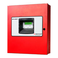
Lists the key features and capabilities of the RP-2002 control panel.
Details the technical specifications, including AC power and output capabilities.
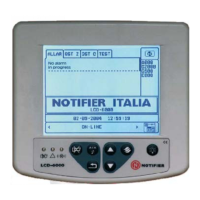
Explains the functionality and features of the 80-character LCD display.
Details the keys available on the FACP for operation and programming.
Describes the sounder used for alarm, trouble, and supervisory conditions.
Lists and explains the function of each front panel indicator light.
Describes the central component containing the system's CPU and interfaces.
Lists optional modules like converters, transmitters, and annunciators.
Details the procedure for mounting the FACP backbox to walls or enclosures.
Details AC power connection requirements and earth ground configuration.
Describes how to connect the battery for backup power.
Explains how to configure a circuit for both waterflow and supervisory devices.
Details the configuration for circuits combining manual release and abort switches.
Describes how output circuits can be used for NACs or releasing solenoids.
Details how to install the module to convert circuits to Class A.
Explains installation of the 4XTM module for municipal box transmission.
Describes the installation of the ANN-SEC card for secondary ANN-BUS.
Provides general guidelines for connecting ANN-BUS devices.
Details wiring requirements and distance calculations for ANN-BUS modules.
Explains how to assign unique addresses to ANN-BUS devices.
Describes the N-ANN-80 LCD annunciator and its installation.
Provides steps for wiring the N-ANN-80 annunciator to the FACP.
Explains how to install the N-ANN-S/PG module for printer connectivity.
Details the N-ANN-I/O module for driving LEDs and graphic annunciators.
Describes the N-ANN-LED module for zone annunciation via LEDs.
Explains the N-ANN-RLY module providing programmable Form-C relays.
Details how to mount the N-ANN-RLY module within the FACP chassis.
Shows the board layout and connection diagram for the N-ANN-RLY module.
Guides the user through the initial programming process using the keypad.
Describes the two user programming levels: Master and Maintenance.
Explains the initial programming steps after system power-up.
Details how programming options are displayed and navigated on the LCD.
Explains how to access programming modes and manage passwords.
Details how to enter and navigate the Master Programming Level.
Explains how to use preprogrammed templates for FACP configuration.
Covers the initial programming and modification of input zones.
Describes how to enable or disable individual input zones.
Explains how to select the type of device connected to an input zone.
Details how to assign output circuits to be activated by input zones.
Explains how to enable temperature supervision for zones.
Describes how to assign custom labels to detectors for identification.
Guides on entering additional descriptive information for programmed devices.
Explains functions for recalling and incrementing text entries.
Covers the configuration options for the panel's output circuits.
Describes how to enable or disable specific output circuits.
Details the various types that can be assigned to output circuits.
Explains supervision options for release circuits.
Describes how NACs can indicate release stages.
Explains options for making output circuits silenceable or non-silenceable.
Details the feature to automatically silence notification appliances.
Explains how to prevent silencing of outputs for a limited time.
Details the various output coding options for notification appliances.
Explains how to synchronize notification appliance activation.
Covers the configuration of cross-zoning for activating outputs.
Details the programming options for the three main circuit board relays.
Explains how to configure various system-wide settings.
Describes the different methods for aborting agent release events.
Covers the configuration of pre-discharge, discharge, and other timers.
Explains how to customize the display banner text.
Details how to set the panel's time, date, and clock format.
Configures audible reminders for ongoing alarms or troubles.
Allows disabling the onboard battery charger.
Configures the FACP for Canadian-specific requirements.
Explains how to enable the secondary ANN-BUS for additional modules.
Covers the configuration and management of ANN-BUS devices.
Details how to enable the ANN-BUS communication.
Explains how to assign addresses to ANN-BUS modules.
Describes the automatic configuration process for ANN-BUS modules.
Details configuration options for the printer interface module.
Shows the mapping of LEDs on the N-ANN-I/O module to system events.
Covers configuration options for the N-ANN-80 annunciator.
Details configuration options for the N-ANN-RLY relay module.
Explains how to view and erase system event history.
Guides on viewing different types of events stored in the history file.
Describes the process of clearing the system's event history.
Covers the procedure for performing system walktests.
Explains how to initiate silent or audible walktests.
Details how to clear the FACP's programmed configuration.
Explains how to change Master and Maintenance level passwords.
Allows enabling or disabling specific input zones for maintenance.
Accesses history logs for viewing or erasing events.
Details how to perform and view results of system walktests.
Covers setting the panel's time, date, and clock format.
Describes the functions of the buttons on the FACP control panel.
Explains how to acknowledge and step through system events.
Details the function of the Alarm Silence key for silencing notification circuits.
Describes the Drill button function for activating system alarms and NACs.
Explains how to reset the FACP and perform a lamp test.
Shows typical LCD messages for input zone trouble conditions.
Explains detector polling for maintenance and freeze conditions.
Explains the timer that prevents silencing of alarms for a set period.
Details the timer for automatically silencing notification appliances.
Configures audible reminders for unresolved troubles.
Allows setting delay times before agent release.
Configures how long agent release continues.
Allows setting a delay for waterflow alarm activation.
Guides on how to enter the Read Status mode.
Allows viewing the programmed FACP configuration template.
Enables viewing the programming details for each input zone.
Allows viewing the programmed options for each output circuit.
Allows viewing the programmed cross-zoning configurations.
Allows viewing the programmed status of on-board relays.
Allows viewing programmed system-wide settings.
Allows viewing programmed timer settings.
Allows viewing programmed daylight saving time settings.
Allows viewing stored system events in the history file.
Guides on printing control panel data to a connected printer.
Allows viewing ANN-BUS settings and device configurations.
Introduces the process of calculating power supply currents and battery needs.
Details how to calculate the required AC branch circuit current.
Explains how to calculate system current draws for different conditions.
Introduces the calculation of system current draws for primary and secondary sources.
Guides on using tables to calculate system current draws for various components.
Provides instructions for calculating the required battery size for standby power.
States NFPA 72 requirements for standby and alarm power duration.
Guides on choosing and placing appropriate batteries for the system.
Introduces the capabilities for mapping circuits and implementing cross-zoning.
Details how to map input zones to directly activate output circuits.
Explains mapping input zones to release circuits, including cross-zoning.
Provides complex examples of cross-zoning and input/output mapping for releases.
Details the configuration for a cross-zone system with horn activation.
Describes how the FACP operates based on Template 1 configuration.
Details the configuration for a single zone system with horn activation.
Describes how the FACP operates based on Template 2 configuration.
Details the configuration for a single hazard system with cross-zoning.
Describes how the FACP operates based on Template 3 configuration.
Details the configuration for a single hazard system with a count-one logic.
Describes how the FACP operates based on Template 4 configuration.
Details a single hazard template with cross-zone NAC activation.
Describes how the FACP operates based on Template 5 configuration.
Details a single hazard template with cross-zone NAC activation.
Describes how the FACP operates based on Template 6 configuration.
Details a cross-zone system template with bell, horn, and strobe activation.
Describes how the FACP operates based on Template 7 configuration.
Details a single hazard template with bell, horn, and strobe activation.
Describes how the FACP operates based on Template 8 configuration.
Details a dual hazard template with cross-zone configuration.
Describes how the FACP operates based on Template 9 configuration.
Details a dual hazard template for single detector applications.
Describes how the FACP operates based on Template 10 configuration.
Details an agent/waterflow template with cross-zone configuration.
Describes how the FACP operates based on Template 11 configuration.
Details an agent/waterflow template for single detector applications.
Describes how the FACP operates based on Template 12 configuration.
Details a template for HP CO2 single detector applications.
Describes how the FACP operates based on Template 13 configuration.
Details equipment needed for NFPA 72 central or remote station service.
Lists equipment required for NFPA 72 auxiliary fire alarm systems.
Outlines requirements for NFPA 72 proprietary fire alarm systems.
Details the steps for performing system tests after installation or maintenance.
Outlines the visual inspection process before applying power.
Describes the procedure for conducting an initial alarm test of the system.
Explains the process for testing installed detectors.
Provides specific testing instructions for i3 series detectors.
Lists the wiring requirements for Notification Appliance Circuits (NACs).
General instructions for operating the FACP.
Location and function of the panel access key.
Explains how to interpret discharge indicators.
Provides immediate actions for alarm conditions.
Provides actions to take when a trouble condition occurs.
Describes the function of the manual release switch.
Explains how to silence alarms and the effect of subsequent alarms.
Describes how to perform a test of all panel indicators and displays.
Details the warranty period and conditions for manufactured products.
Explains the process for submitting and handling warranty claims.
| Model | RP-2002C |
|---|---|
| Type | Fire Alarm Control Panel |
| Number of Zones | 2 |
| NAC Circuits | 2 |
| Operating Temperature Range | 32°F to 120°F (0°C to 49°C) |
| Output Current | 3.0 A |
| Battery Capacity | Up to 18 Ah |
| SLC Style | Style 4, 6, or 7 |
| Relative Humidity | 10% to 93% non-condensing |


