RP-2002 Series Manual — P/N 53039:E6 1/26/2017 31
Installation of Optional Modules Installation
2.6 Installation of Optional Modules
2.6.1 N-CAC-5X Class A Converter Module
Installation
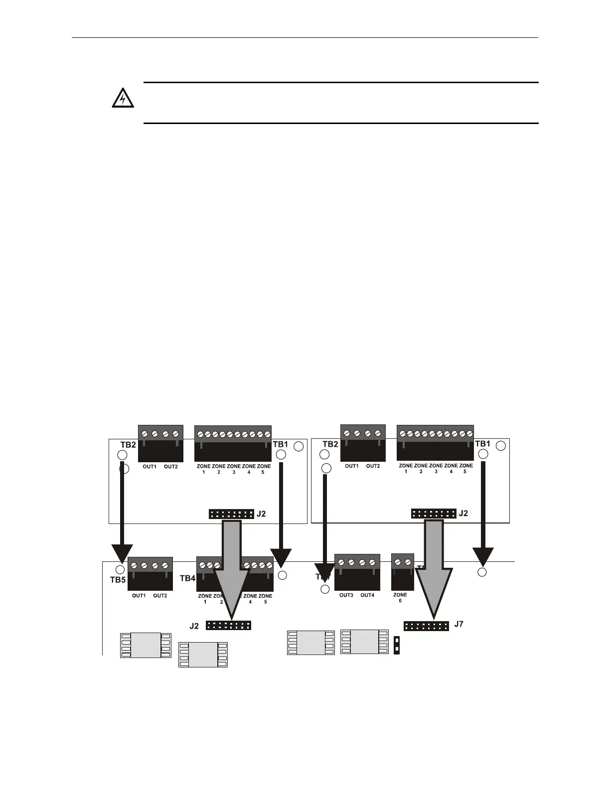
The N-CAC-5X Module can be used to convert five Style B (Class B) Initiating Device Circuits to
Style D (Class A) and the two Style Y (Class B) Notification Appliance Circuits to Style Z (Class
A). Two N-CAC-5X Modules are required to convert all Output Circuits and/or Initiating Device
Circuits to Class A. The modules plug into connector J2 which is located at the top left of the main
circuit board and J7 which is located at the top center of the main circuit board.
To install the N-CAC-5X, remove the two main circuit board mounting screws referenced in the
following illustration and replace with the two supplied male/female standoffs in the locations indi-
cated in the following figure. Carefully align the connector on the N-CAC-5X with J2 on the FACP
main circuit board and press the module securely into place. Make certain the pins are properly
aligned to prevent bending or breaking of any connector pins. Secure the N-CAC-5X to the stand-
offs with the screws that were just removed.
To install the second N-CAC-5X on J7, remove the main circuit board mounting screw referenced
in the following illustration and replace with the supplied male/female standoff. Insert the supplied
plastic standoff in the location indicated in the following illustration. Carefully align the connector
on the N-CAC-5X with J7 and press the module securely into place. Make certain the pins are
properly aligned to prevent bending or breaking of any connector pins. Secure the N-CAC-5X to
the metal standoff with the screw that was just removed.
WARNING: RISK OF ELECTRICAL SHOCK AND EQUIPMENT DAMAGE
DISCONNECT ALL SOURCES OF POWER (AC AND DC) BEFORE INSTALLING OR REMOVING
ANY MODULES OR WIRING.
Figure 2.13 N-CAC-5X Module Installation
Main Circuit Board
Metal
Standoff
Plastic
Standoff
N-CAC-5X Module
rp2001cac5mnt.cdr
N-CAC-5X Module
Metal
Standoff
Metal
Standoff
Installation on J2 Connector
Installation on J7 Connector

 Loading...


