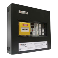
Do you have a question about the Honeywell Notifier RP-2001 and is the answer not in the manual?
Discusses the limitations of fire alarm and emergency communication systems.
Covers essential safety warnings and general installation guidelines.
Lists the key capabilities and functionalities of the RP-2001 control panel.
Details technical specifications like AC power, current draw, and circuit types.
Describes the panel's LCD display, keypad, sounder, and status indicators.
Identifies major hardware components like the main circuit board and power supply.
Lists available add-on modules and accessories for expanded functionality.
Provides instructions and considerations for physically mounting the control panel.
Details the procedures for connecting AC and battery power sources.
Explains how to connect and configure initiating device circuits (IDCs).
Covers the configuration and connection of notification appliance and releasing circuits.
Specifies rules for separating power-limited and nonpower-limited wiring.
Step-by-step guide for installing various optional modules like N-CAC-5X.
Information on connecting and configuring ANN-BUS devices and wiring.
Overview of the user programming interface and procedures.
Accessing and using the master programming functions for configuration.
Detailed steps for programming and configuring input zones.
Configuration options for output circuits, including coding and silence settings.
Setting up cross-zoning logic for activating outputs based on multiple inputs.
Configuration of system-wide settings like timers, banner, and clock.
Explains the function of each button on the control panel keypad.
Describes the meaning of each status indicator light on the panel.
Details the system's behavior and display during normal, non-alarm conditions.
How the system indicates and reports trouble conditions.
How the system behaves and displays information during an alarm condition.
How the system handles and indicates supervisory events.
How to view programmed features and system status without altering settings.
Introduces the process for calculating power supply and battery requirements.
Details how to determine the necessary AC power circuit requirements.
Method for calculating total current draw for system components.
Steps to determine the appropriate battery size based on load calculations.
Explains how input zones can be mapped to output circuits and cross-zoned.
Examples of mapping input zones to directly activate output circuits.
Examples of mapping input zones for activating release circuits via cross-zoning.
Details the configuration for a single hazard, 3-zone setup.
Configuration for a cross-zone setup with manual release capability.
Configuration for a dual hazard system with combined release logic.
Configuration for a dual hazard system with split release logic.
Configuration for a single hazard system with low pressure monitoring.
Configuration for a single hazard system with cross-zoned inputs.
Configuration for a single hazard system with dual zones.
Requirements for implementing the system under NFPA 72 Auxiliary Fire Alarm System.
Requirements for connecting to remote station signaling systems.
Requirements for proprietary protective signaling system configurations.
Details connecting the panel to central/remote station transmitters via dry contacts.
Visual checks to be performed after installation before applying power.
Procedure for testing the system's alarm functions after installation.
Steps for testing individual smoke detectors after installation or maintenance.
Guidelines for regular inspection, testing, and maintenance of the control panel.
Specifies wire gauge and length requirements for Notification Appliance Circuits.
Outlines the manufacturer's warranty terms and conditions for the products.
Details the process for submitting and handling warranty claims.
| Model | RP-2001 |
|---|---|
| Type | Fire Alarm Control Panel |
| SLC Loops | 1 |
| NAC Circuits | 2 |
| Operating Voltage | 24V DC |
| Operating Temperature | 32°F to 120°F (0°C to 49°C) |
| Humidity Range | 10% to 93% non-condensing |
| Power | 120 VAC, 60 Hz |
| Certifications | UL, FM, MEA |


