36 RP-2001 Series Manual — P/N 52985:D5 1/26/2017
Installation ANN-BUS Devices
Wiring Configuration
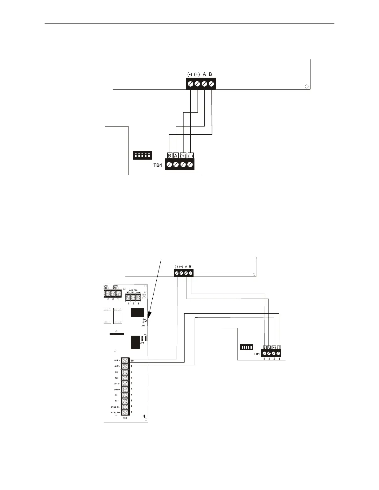
Figure 2.16 illustrates the wiring between the FACP and ANN-BUS devices.
Powering ANN-BUS Devices from Auxiliary Power Supply
Figure 2.17 illustrates the powering of ANN-BUS devices from an auxiliary power supply such as
the FCPS-24S6/8, when the maximum number of ANN-BUS devices exceeds the ANN-BUS
power requirements.
Figure 2.16 FACP wiring to ANN-BUS Device
FACP
N-ANN-80
ANN-BUS and power wiring are
supervised and power-limited
TB3
aan80toRP2001.cdr
Primary ANN-BUS
Figure 2.17 Powering ANN-BUS Devices from FCPS-24S6/8
N-ANN-80
FACP
FCPS-24S6/8
+24 VDC
-24 VDC
ANN-BUS
Cut Ground Fault Detection jumper JP1 (FACP monitors for ground faults)
ANN-BUS and power wiring are
supervised and power-limited
TB3
ann80toFCPSrp2001.cdr
Primary ANN-BUS

 Loading...


