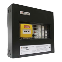
Do you have a question about the Honeywell Notifier ID60 and is the answer not in the manual?
Provides rules for bringing cables into the back box and ensuring safe installation.
Details checks for RS485, RS232, DC Auxiliary, and Sounder circuits.
Guides on powering the panel, connecting batteries, and selecting language.
Introduces configuration sections, navigation, and access levels.
Configures device options, ports, protocols, and system settings.
Manually learns SLC devices, configures module types, and sets CBE rules.
Describes faults related to loop wiring, like open, short, and partial shorts.
Covers faults related to power supply, batteries, and the control panel's processor.
Describes setting up a monitored fault routing output using a zone module and panel menus.
| Standby Current | 150 mA |
|---|---|
| Humidity Range | 10% to 93% non-condensing |
| Communication Protocol | CLIP (Classic Loop Interface Protocol) |
| Power Supply Current | 3.0 A |
| Auxiliary Power | 24 VDC @ 500 mA |
| Operating Voltage | 24 VDC |
| Operating Temperature | 0°C to 49°C (32°F to 120°F) |


