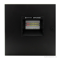
Do you have a question about the Honeywell Notifier ID50 and is the answer not in the manual?
Lists essential criteria to meet before installing the panel to prevent damage or performance issues.
Instructs on inspecting the panel for any damage that may have occurred during transit.
Provides steps for reporting and returning damaged or suspect equipment to the supplier.
Describes how to safely dismantle the panel for installation purposes, emphasizing component removal.
Details the procedure for safely removing the panel cover, including screw removal and earth lead disconnection.
Explains how to remove the PCB assembly, emphasizing anti-static precautions and configuration backup.
Details the procedure for securely fixing the back box to the wall, including flatness requirements.
Guides on reassembling the panel after installation, including PCB, labels, and wiring connections.
Details how to connect the panel to an RS485 communications link for repeaters or mimics.
Explains the procedure for fitting the RS485 interface module onto the PCB assembly.
Describes how to connect the panel to RS232 devices for configuration or software upgrades.
Provides general rules for cable installation, compliance with regulations, and mains supply precautions.
Guides on bringing cables into the back box and their specific termination points on the PCB.
Emphasizes the importance of cable quality, screening, resistance, and capacitance for system reliability.
Lists essential checks to perform before connecting mains power to ensure correct installation.
Describes internal checks, including PCB fitting and jumper link options for software updates.
Explains the function of the Software Upgrade (J4) and Configuration Lock (J9) jumpers.
Lists sections detailing procedures for checking and connecting the external wiring to the panel.
Details checks and connection procedures for analogue addressable loop pairs, including resistance limits.
Describes connecting the RS485 Communications Link to the panel's terminal block TB6.
Lists checks required before connecting any circuit to the monitored DC Auxiliary Output.
Explains configuring sounder circuits with resistor or diode end-of-line devices for EN54 compliance.
Details testing sounder circuits with resistor EOL devices and checking resistance values.
Describes testing sounder circuits using diode EOL devices and setting sounder fault monitoring type.
Explains configuring CFG Outputs C and D as sounder or relay outputs using jumper links.
Details the step-by-step procedure for powering up the ID50 Series panel safely.
Provides instructions for connecting and handling batteries, including safety precautions.
Describes panel configuration via the 'Commission' menu and preparing for user handover.
Lists tests to be performed after configuration to verify panel operation.
Describes Level 3 configuration options and the importance of the memory lock jumper.
Introduces the Setup options menu for configuring site-specific panel settings.
Allows configuration of basic panel settings like language, date format, and access levels.
Configures system inputs and outputs, including device blinking and output pulse ratios.
Configures the panel to test each device on the loop at a specified time.
Configures the evacuation period delay for extinguishing systems, up to 180 seconds.
Sets up the connection of peripheral equipment via the RS232 and RS485 communication ports.
Configures the panel for GSM module event messaging, including PIN, phone numbers, and event notifications.
Allows configuration of Day/Night settings, including Day Mode Activity.
Allows manual configuration, learning, or viewing of Signalling Line Circuit and On-Board Output Circuits.
Enables manual configuration of devices to a pre-configured analogue addressable SLC loop.
Assigns a specific device to a specific zone, with a maximum of 32 zones available.
Allows changing sensor sensitivity values for alarm, day, and group settings.
Configures module types for input and output devices and their associated actions.
Configures Control-By-Event rules, enabling modules to be assigned to specific rules.
Provides automatic recognition and learning of devices connected to the SLC loop.
Permits configuration of the panel's six On-Board Output Circuits.
Allows configuration of the panel's on-board output circuits to various types.
Assigns each of the panel's on-board output circuits to a CBE Rule range.
Allows configuration and viewing of the 64 available Control-By-Event (CBE) Output Rules.
Selects the type for CBE Output Rules, such as FIRE, FAULT, or PLANT.
Determines output response when a zone detects an alarm, configurable per zone status.
Configures user and engineer access passcodes for panel configuration.
Details operating voltage, tolerances, battery charger output, and DC auxiliary output.
Lists fire-resistant cables for signalling loops and sounder circuits, with standard and enhanced types.
Explains VIEWTM sensor sensitivity settings, levels, and obscuration percentages.
Details the calibration process for VIEWTM sensors upon first operation with the panel.
Explains how to learn VIEWTM sensors and configure their type (AVS or AVR).
Describes configuring sensitivity levels for alarm, day, and group settings for VIEWTM sensors.
Lists common loop wiring fault messages and their possible causes and remedies.
Lists fault messages related to power supply issues like PSU overvoltage or mains failure.
Describes setting up a monitored fault routing output using a sounder output, input module, and termination unit.
| Brand | Honeywell |
|---|---|
| Model | Notifier ID50 |
| Category | Control Panel |
| Language | English |


