ID50 Series Panel - Installation, Commissioning & Configuration Manual
Appendix 5 - Fault Routing Output Configuration
A5 - 1
997-263-000-11, Issue 11
January 2010
Appendix 5
Configuration of Fault Routing Output
Using a Zone Module
A monitored fault routing output can be set up using a
sounder output configured as a fault relay output, an input
module (M710-CZ) and an RTU01 Routing Termination
Unit. The connection between the input module and the
third-party fault routing equipment is monitored by the
RTU01 which is located at the fault routing equipment
end of the monitored circuit.
The contol panel back box has provision for mounting the
module internally; threaded fixing points allow the module
to be fitted in either of two positions at the bottom of the
box (either side of the standby batteries). The M710-CZ
module uses an address on the loop and can be configured
(using the panel menus or off-line configuration tool) to
provide a fault indication should a comms fault occur
between the zone monitor module and the RTU01.
Configuring the Fault Routing Output
If the M710-CZ module is configured using the learn
operation it is displayed in the panel menus as a ZMX
device type. To change the operation of the module to a
fault-routing fault monitor navigate to the module editing
screen: 5:Commission/2:Circuit/1:SLC loop/
1:Devices/2: Modules and then change the module type
to ‘FRM’ (Fault Routing Module). The module type change
is saved when exiting this menu.
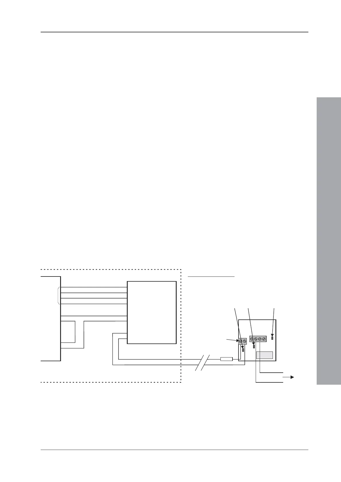
Fire Control Panel
M710-CZ
1
2
3
4
6
7
9
10
Loop
AUX
24V
Fault Relay
VFC
RTU01
-
-
+
+
C
N/O
820R
AB C
3rd Party
Router
N/O
C
See
Note 2
RTU01 Unit - links
Link A - fitted
Link B - not fitted
Link C - not fitted.
Notes:
1 To avoid a fault condition, the 820R resistor must be
in line with the connection to the + terminal of the
RTU01 PCB 2-way connector.
2 If the module reports open-circuit faults for the FRM,
fit the end-of-line capacitor supplied with the M710-
CZ module across the + and - terminals of the RTU01.

 Loading...


