ID50 Series Panel - Installation, Commissioning & Configuration Manual
Commissioning
32997-263-000-11, Issue 11
January 2010
POWER
PLANT ALARM
RESET
FIRE
DISABLEMENT FAULT
TEST
POWER SUPPLY FAULT
EARTH FAULT
POWER
PLANT ALARM
FIRE OUTPUT ACTIVE
DELAYS ACTIVE
FIRE OUTPUT: FAULT / DISABLED
FIRE CONTROL O/P: FAULT / DISABLED
PRE- ALARM
SYSTEM FAULT
SOUNDER: FAULT / DISABLED
Status: NORMAL
Sat 05/01/2002 00:00:00
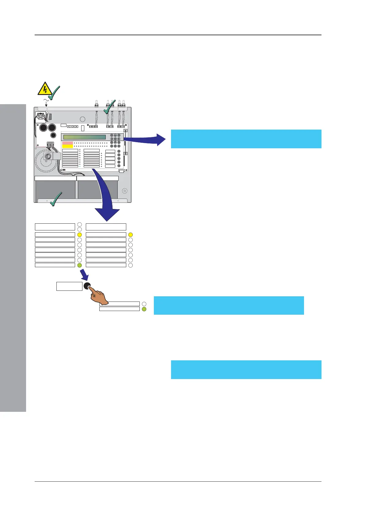
4.5 Powering the Panel
To power up an ID50 Series panel:
1 Ensure all wiring is terminated correctly and all PCBs
are fitted correctly.
2 With the batteries in the back box, connect the mains/
battery supply wiring plug to the power socket, between
the transformer secondary fuse (FT1) and the battery fuse
(FC1). Turn on the mains supply. The panel will display
CPU RESTART with the buzzer sounding, and the FAULT,
SYSTEM FAULT and ‘POWER’ LEDs will illuminate.
3 Connect the battery power supply (refer to
Section 4.5.2 Batteries).
4 When powered up, press the RESET button (then enter
an appropriate access code if required). The panel should
settle to a quiescent state. The LCD should display the
‘Status: NORMAL’ message unless fault(s) are present
on the system. The internal buzzer will sound intermittently.
Note: If the panel indicates fault(s) are present, clear
them before you proceed further with the
commissioning procedure.
5 When all fault LEDs have been extinguished, the
system is ready for testing, see Section 4.7,
Commissioning Tests.
Note: The panel may be powered up satisfactorily from
batteries alone. However, first ensure the batteries are
fully charged to avoid the risk of the panel powering
down due to insufficient voltage being available.
3
2
1
4.5.1Start-up Language Selection
At panel start-up, and with a non-configured memory, you
will be prompted to select the appropriate panel language
from a displayed screen similar to the one below:
Press the appropriate numeric pushbutton to select the
desired language. If a selection is not made within 30 secs
the panel will use the first language listed. The list of
languages may vary from those listed above.
Note: If the memory is unlocked (refer to Section 4.3.1 Jumper
Link Options) selection of the desired language will be
stored and this language will be used the next time the
panel is re-started. If the memory is locked when a
language selection is made, the panel will not store this
change and the Startup Language screen will be
displayed again at the next panel startup. However, the
language can be changed at any other time using
the ‘Language’ setup menu (refer to Section 5.5.1).
1: English 2: España 3: Portugues
4: Islanska 5: Italiano
FIRE
DISABLEMENT
ID50 FIRE CONTROL PANEL
Complies with EN54-2/4 1997
Period of Manufacture 1999
FAULT
RESET
EXTEND DELAY
TEST
POWER SUPPLY FAULT
EARTH FAULT
POWER
PLANT ALARM
FIRE OUTPUT ACTIVE
DELAYS ACTIVE
FIRE OUTPUT: FAULT / DISABLED
FIRE CONTROL O/P: FAULT/ DISABLED
PRE- ALARM
SYSTEM FAULT
SOUNDER: FAULT / DISABLED
MUTE BUZZER
SILENCE/
RESOUND
END DELAY/
EVACUATE
12
3
4
56
7
8910
11 12
13
14
15 16
ZONE FIRE
ZONE FAULT
DISABLE/TEST
00..9
31
2
46
7
5
[
98
FAULT 01/01 00:00
CPU RESTART

 Loading...


