ID50 Series Panel - Installation, Commissioning & Configuration Manual
Appendix 2 - ID60 Panel Differences
A2 - 3
997-263-000-11, Issue 11
January 2010
VIEW
TM
sensors remain
inoperable for 60 seconds
after being replaced
while calibrating
VIEW
TM
Co-operative Multi-sensing
Co-operative sensing is carried out automatically between
VIEW
TM
sensors in the same group and across sensor
type. Grouped sensors co-operate within the group
providing greater levels of sensitivity with a reduced risk
of false alarms. When first installed, VIEW
TM
sensors are
all allocated to group 1 but they can be configured in up
to 50 groups. Sensors allocated to group ‘0’ operate
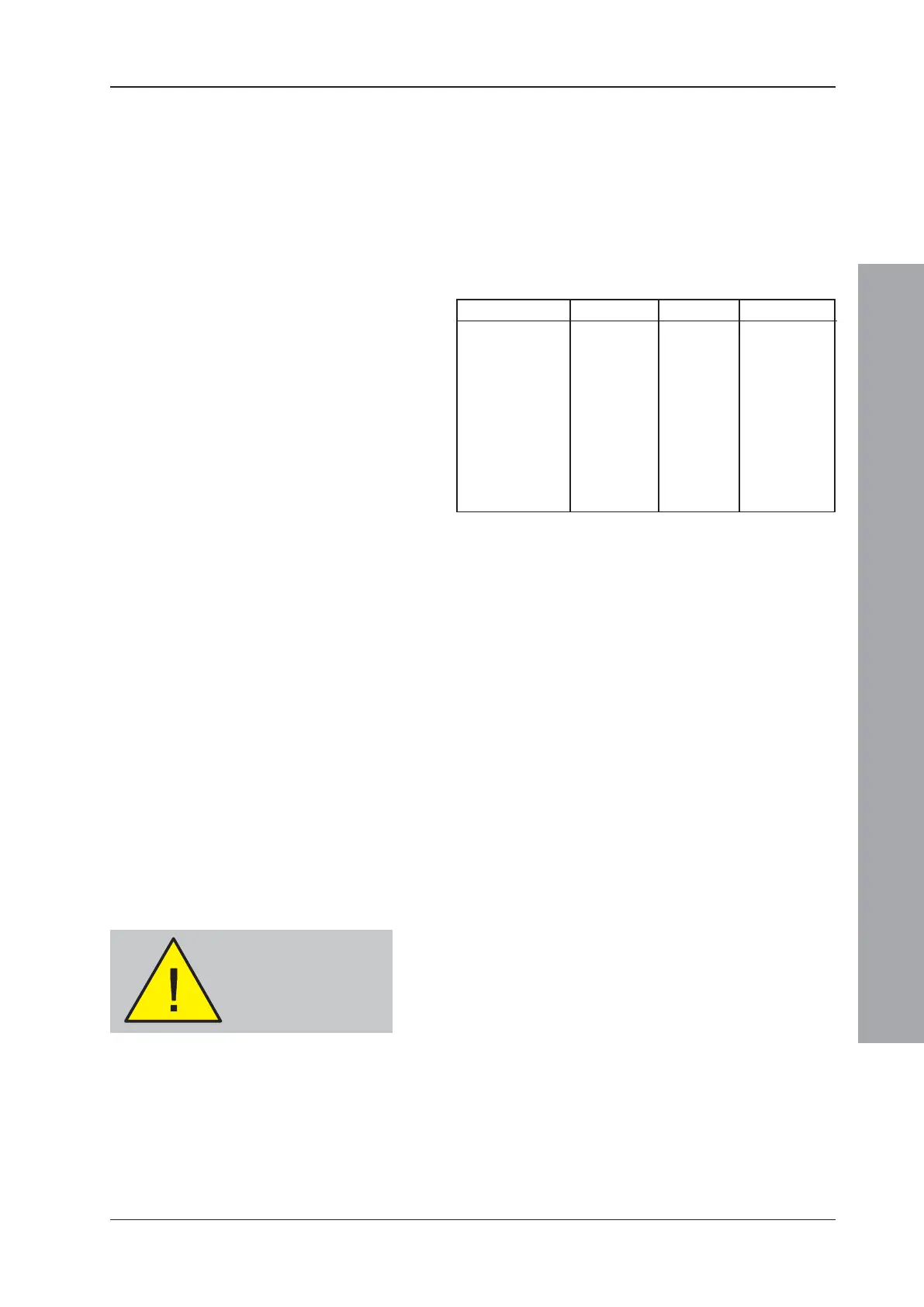
independently. An example of VIEW
TM
sensor co-
operative grouping is given below:
Address Type Zone Group
03 AVS 1 01
04 AVS 1 02
05 AVS 1 02
09 AVR 1 01
10 AVS 1 02
11 AVS 1 00
15 AVS 2 01
16 AVS 2 01
17 AVS 2 02
27 AVS 2 01
Each group can have one or more VIEW
TM
sensors
configured as reference sensors (AVR). Sensors placed
such that external smoke influences (eg. bonfires and
exhaust fumes) can be detected early should be
configured as AVRs. When these influences are detected
by the AVR the group can then be temporarily desensitised.
VIEW
TM
Sensor Sensitivity
Most local codes of practice require very low levels of alarm
sensitivity selection be tested on-site before implementation.
Alarm sensitivity level 6 (L6) and below generally require
a 90-day test to ensure the sensor environment is suitable
for a higher sensitivity setting. This is not required for
high levels of pre-alarm sensitivity selection.
Dynamic Intelligent Grouping (DIG) Operation
The Dynamic Intelligent Grouping (DIG) Operation only
performs calculations on up to five sensors with the highest
value. This is an advantage in a group of many sensors, as
any condition will quickly be recognised by the panel.
A2.1 Calibrating VIEW
TM
Sensors
Each VIEW
TM
sensor is automatically calibrated on first
operation with the panel. This calibration is completed at
one of the following times:
a. Approximately 90 secs after the panel is powered on.
b. 60 secs after the sensor is installed on a panel which
is already operating normally.
During this initial period (which is required to allow the
VIEW
TM
sensor to stabilise) the sensor must not be
exposed to smoke or other abnormal conditions,
otherwise the panel may report a sensor fault.
If a VIEW
TM
sensor is removed from the operational loop,
or communication with the panel is broken for a minimum
of 30 secs, recalibration will take place automatically.
Note: If a VIEW
TM
sensor is removed and cleaned, or
replaced with a new one, wait at least 30 secs after
removal before replacing it.

 Loading...


