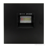
ID50 Series Panel - Installation, Commissioning & Configuration Manual
Appendix 1 - Specifications
A1 - 4997-263-000-11, Issue 11
January 2010
Volt-free Contact (VFC) Output Rating
Type: Single-pole change-over
Maximum load: Contacts rated 30V 1A
Fuse rating: Not applicable
Switched -VE Output Rating
Output voltage: 16 to 30V
Maximum load: 83mA (total for both outputs)
Loop Output
Output voltage: 22.5 to 26.4V.
Maximum load
1
: 0.5A peak current*
Max. loop impedance**: 20 ohms (-ve cable only, with
duplicate address detection) or 40
ohms (-ve cable only, without
duplicate address detection).
Max. loop capacitance: 0.5μF
1
The panel (software version 5.04, or later) is compatible with
the Loop Booster Module (LBM). The LBM provides
additional power to the loop for output modules during panel
alarm conditions. Refer to the instructions (997-509-000-X)
provided with the LBM for a complete technical specification.
Up to 198 loop devices (up to 99 sensors and 99 modules) may
be fitted to the analogue loop.
The communication with devices on the loop can use either the
Notifier ‘CLIP’ or OPAL polling protocol. Refer to Hardware
Recommendations for a list of compatible devices and loading
limitations.
DC Auxiliary Rating
Output voltage range: 17.1 to 30V
Maximum load: 250mA
Quiescent: 150mA*
Alarm: 0.25A*
Cables should be capable of
carrying a minimum 1A.
Fuse rating: Not applicable
Note: It is recommended that the auxiliary output
should not be used in the quiescent state other
than to provide a supply to drive ancillary devices’
power indicators.
RS485 Serial Port (Optional)
Isolation: Functional at 30V.
Baud rate: 1200 Baud.
Connector: Terminal block on RS485 Interface
Module PCB.
Maximum cable length: 1200metres (minimum of 1.5mm
2
screened cable recommended)
* Total system load is limited by the
transformer output
1
. The Notifier Loop
and Battery Calculator Support Tool,
should be used to ensure that the system
is NOT overloaded.
** Use the following loop driver source
impedance values for panel calculation
purposes: 3.8R at 22.5Vdc

 Loading...


