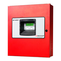
Do you have a question about the Honeywell NOTIFIER RP1r and is the answer not in the manual?
Explains the manual's objective, scope, and intended audience for the RP1r panel.
Covers pre-installation checks, system design, and planning considerations for the panel.
Details the panel's CE marking and conformance to relevant European Community Directives.
Provides an overview of the RP1r control panel, its design, and general characteristics.
Lists the primary features, microprocessors, power supply, and connectivity of the panel.
Covers general cabling instructions, EMC requirements, and mains supply wiring.
Illustrates the layout and terminal connections of the release control panel board.
Details wiring procedures for detection zones, including terminal blocks and EOL resistors.
Explains the correct wiring method for polarized sounders and monitoring circuits.
Describes how to connect Normally Open and Normally Closed monitored inputs.
Details wiring for various relays including general alarm, status, and fault relays.
Covers wiring for 24Vdc outputs, including resettable and non-resettable supplies.
Explains the function and connection of the digital input for external control.
Describes the optional keyswitch for level 2 access and its installation.
Details the Automatic, Manual only, and System disabled operating modes of the panel.
Explains the different access levels (1, 2, 3) and how to gain access.
Describes the panel's status indicators and fault relay behavior under normal conditions.
Outlines the panel's response and activation during a single zone fire alarm.
Details the panel's transition to activated mode and release sequence upon double alarm.
| Brand | Honeywell |
|---|---|
| Model | NOTIFIER RP1r |
| Category | Control Panel |
| Language | English |


 Loading...