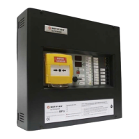
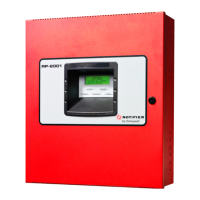
Extinguishing control panel. User manual
22 June 2011 1
CONTENTS
1. Introduction............................................................................................................................................. 2
1.1 Manual Purpose................................................................................................................................. 2
1.2 Before Installation .............................................................................................................................. 2
1.3 System Design and Planning............................................................................................................. 2
1.4. CE Marking........................................................................................................................................ 2
1.5. General.............................................................................................................................................. 3
1.6 Release control panel main features ................................................................................................. 4
1.7 Cabling ...............................................................................................................................................8
2. CONNECTIONS AND WIRING................................................................................................................ 9
2.1 Release control panel board diagram................................................................................................ 9
2.2 Detection zone wiring....................................................................................................................... 11
2.3 Sounder circuit wiring....................................................................................................................... 12
2.4 Connection to monitored inputs ....................................................................................................... 12
2.5 Relay wiring...................................................................................................................................... 13
2.6 24Vdc supply wiring ......................................................................................................................... 14
2.7 Digital input ...................................................................................................................................... 15
2.8 User Keyswitch (level 2)................................................................................................................... 15
3. System operation ................................................................................................................................. 17
3.1 Release control panel operating modes: ......................................................................................... 17
3.2 Access levels ................................................................................................................................... 17
3.3 Normal condition .............................................................................................................................. 17
3.4 Single zone fire condition (Pre-activated) ........................................................................................ 18
3.5 Double zone alarm condition. (Activated) ........................................................................................ 18
3.6 Delay time before extinguishing release activation.......................................................................... 19
3.7 Extinguishing release....................................................................................................................... 19
3.8 Signal representing the flow of extinguishing agent ........................................................................ 19
3.9 Low pressure signal ......................................................................................................................... 19
3.10 Open door signal............................................................................................................................ 20
3.11 Hold device .................................................................................................................................... 20
3.12 Emergency Abort device................................................................................................................ 21
3.13 Manual release delay..................................................................................................................... 19
3.14 End of extinguishing signal ............................................................................................................ 21
3.15 Silence sounders............................................................................................................................ 21
3.16 Sounder delay (Pre-activated status)............................................................................................. 22
3.17 Control of flooding time or soak time (“dr” parameter)................................................................... 23
3.18 Evacuate ........................................................................................................................................ 23
3.19 Lamp test ....................................................................................................................................... 24
3.20 Reset.............................................................................................................................................. 24
3.21 Disable zones................................................................................................................................. 24
3.22 Disable the extinguishing process ................................................................................................. 24
3.23 Monitored circuits faults ................................................................................................................. 25
3.24 Activation of the Release 2 output ................................................................................................. 25
4. Programming mode.............................................................................................................................. 26
4.1 Microswitches configuration............................................................................................................. 29
5. Special functions.................................................................................................................................. 32
(EN54 non-compliance)............................................................................................................................ 32

 Loading...


