Extinguishing control panel. User manual
22 June 2011 12
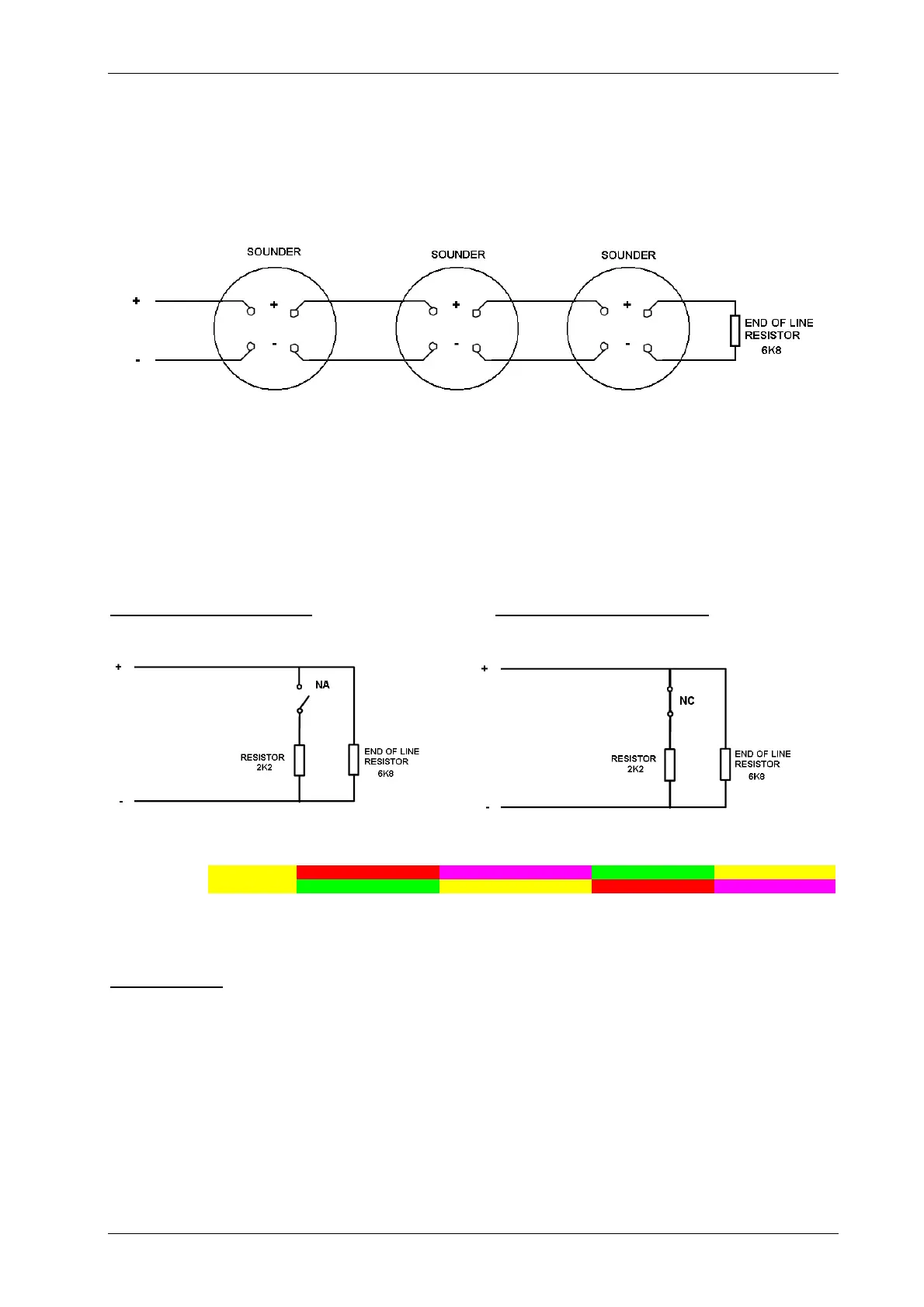
2.3 Sounder circuit wiring. Terminal blocks: 18 and 19
All sounders must be of the polarised type. In non-polarised sounders are used, the control panel will
permanently show a fault condition, and therefore, a polarisation diode should be installed in the sounder.
Sounder circuits must be wired as a single circuit with no spurs or T junctions to enable the monitoring
circuit to work correctly.
NOTE: The above drawing shows the polarity when sounders are activated. When sounders are
in stand-by, the sounder polarity is reversed.
2.4 Connection to monitored inputs
By default, all monitored inputs are Normally Open (NO) contacts and they are activated when the circuit
is closed with a 2K2 resistor.
Normally Open Circuit (NO)
Normally Closed Circuit (NC)
% 0 15 26 40 80 100
Description NO Short circuit Activation NO 2K2//6K8
ctivation NO without EOL 2K
Normal Status 6K8 Open circuit
Description NC Short circuit Normal Status 2K2//6K8 Only 2K2 Only 6K8 Open circuit
Resistor 0 ------------- 680 1K ---------------------- 1K5 2K ------------------------ 3K 4K7 ------ 6K8 ------- 8K > 10K
(Approximate values)
Important note:
In Normally Open (NO) circuits, when the R=2K2 line is closed, the input becomes ACTIVE, even if
the EOL resistor (6K8) is not detected. In this case (ACTIVE input with EOL resistor not detected), a
fault will also be indicated.
In Normally Closed (NC) circuits, when the R=2K2 line is open, the input becomes ACTIVE, even if
the EOL resistor (6k8) is not detected. In this case (ACTIVE input with EOL resistor not detected), a
fault will also be detected.

 Loading...


