Extinguishing control panel. User manual
22 June 2011 14
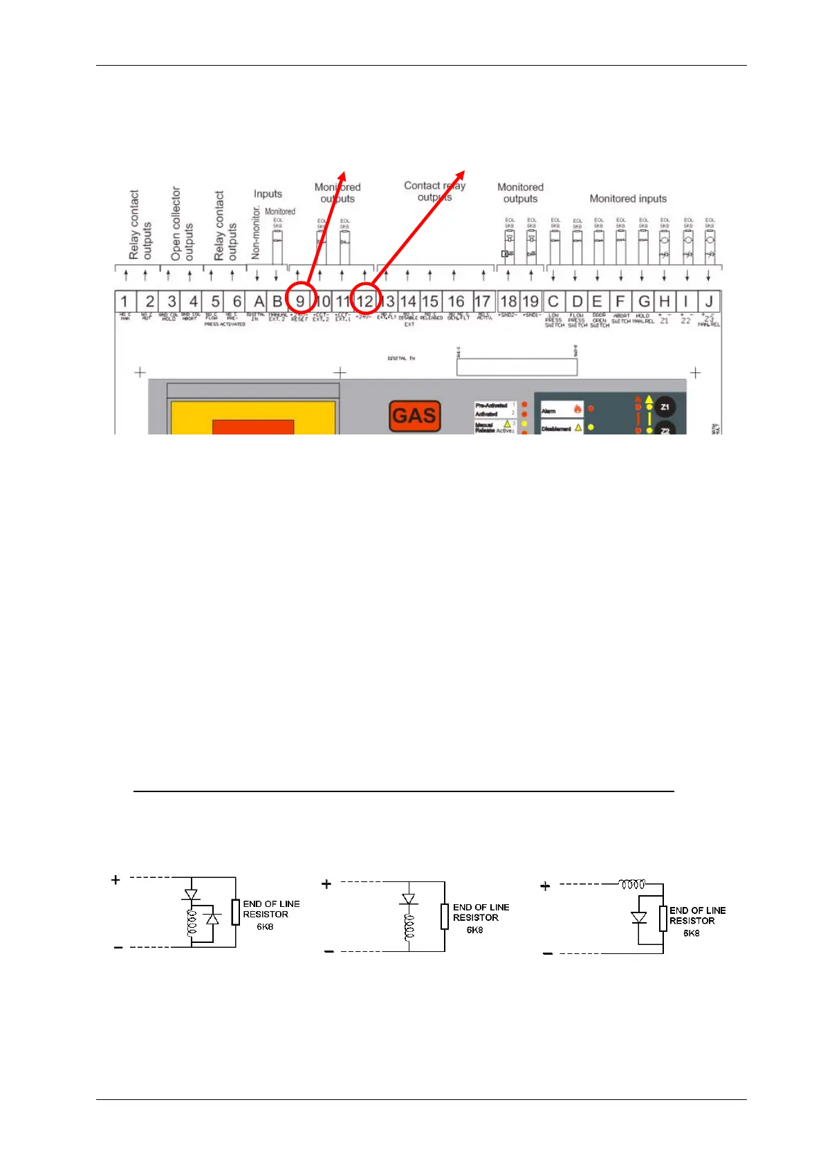
2.6 24Vdc supply wiring. Terminal blocks: 9 and 12
The Release control panel has two 24Vdc outputs, supplied by the control panel power supply.
The maximum current between both outputs is 500mA, protected with electronic fuse.
Aux 24V fixed voltage output provides constant 24V and a maximum current of 250mA to supply
auxiliary devices.
Res 24V resettable voltage output and 250mA provides resettable supply. The voltage goes down
to 0V for 5 seconds, each time the control panel is reset. This output is used to supply power to
external devices that need to switch off the power supply in order to be reset.
Before connecting external devices to the control panel, please check the current that they require.
Bear in mind the power usage of the system in alarm and stand-by. Make sure that the control
panel power supply and battery have enough capacity, otherwise use suitable external power
supply units. In order to calculate the power consumption, please refer to the technical
specifications of this manual and of the devices to be connected.
To connect holder coils, relays or valves, refer to the diagram below. Make the connections
as indicated in the drawing; otherwise the control panel may be damaged.
2.6 b Solenoid wiring (the following drawing shows the polarity when the system is activated)
Terminal blocks: 10 and 11
Different options depending on the solenoid:
Note: The polarity shown in the above drawing is the corresponding to the ACTIVATE status of
Ext 1 and Ext 2 outputs (10 and 11 in the Release control panel board). When the system is in
stand-by, the polarity is reversed. The maximum current per release circuit is 1Amp. (Remember
that the max. Current supplied by the control panel power supply is 2.4Amp).
Resettable
Non-resettable

 Loading...


