Extinguishing control panel. User manual
22 June 2011 13
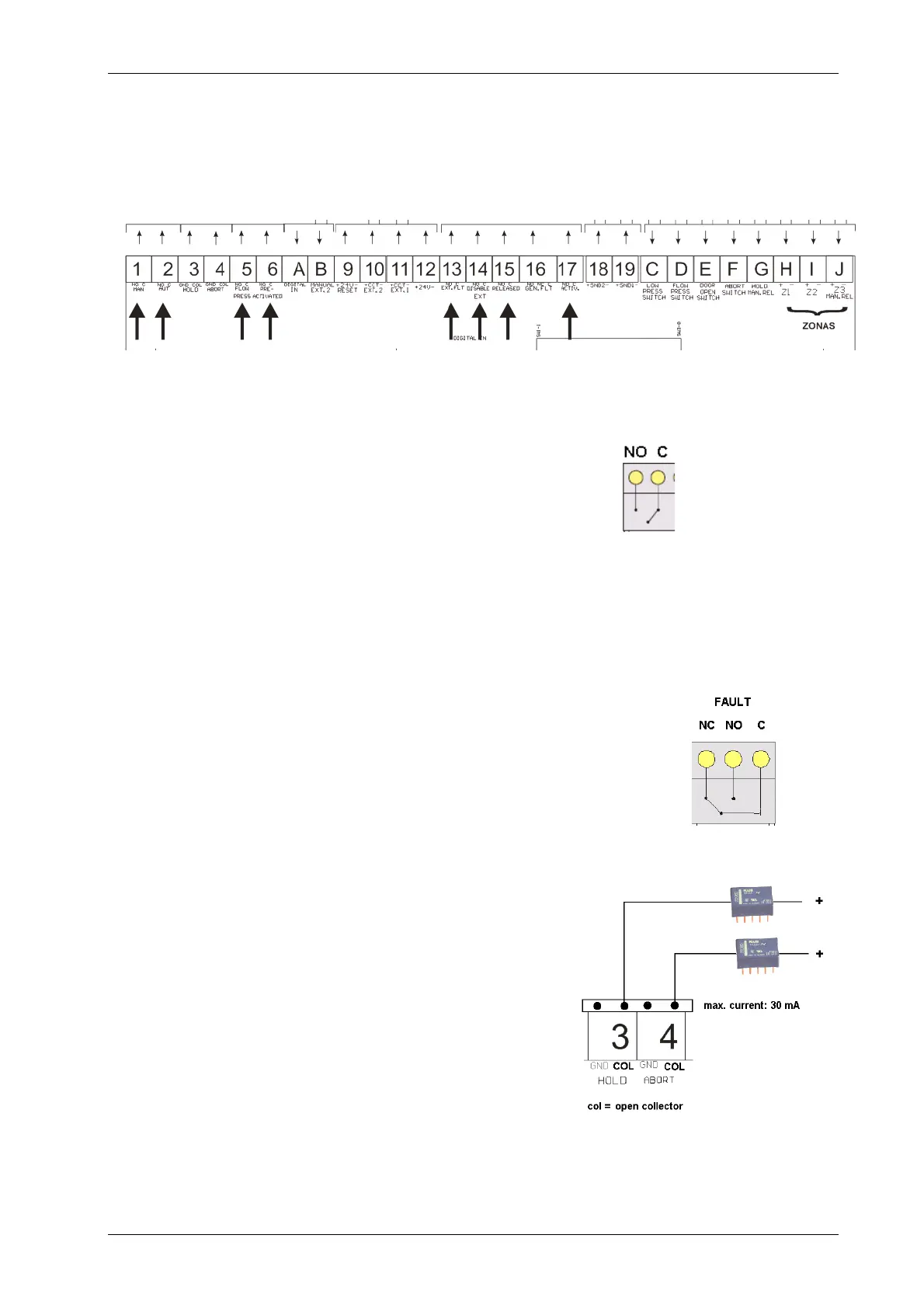
2.5 Relay wiring. Terminal blocks: 1, 2, 5, 6, 13, 14, 15 and 17
Wiring suitable for the following relays (see drawing on the right):
o General alarm (preactivation)
o Release process activation (coincidence)
o Evacuate,
o Release in process
o Release circuit fault
o Flow pressure switch
o Status:
Manual
Automatic and
System disabled.
Fault relay wiring. Terminal blocks: 16
The fault relay is activated in stand-by status and deactivated when there
is a fault in the control panel or when the control panel power is switched
off. Faults can be configured as resettable or latched. Faults are latched
by default and the panel has to be reset for the relay to return to stand-
by. On the contrary, the resettable faults make the relay return to stand-
by automatically, when the fault disappears.
Open collector outputs. Terminal blocks: 3 and 4
The open collector output indicates the release in:
o Hold Mode
o Abort Mode

 Loading...


